Remove a Pulley on C&P 10x15 New Style
I have a C&P New Style - according to the serial number it was manufactured in 1928 - we need to remove the guard and in order to do that I have to remove the big pulley that holds the belt first..
We’ve loosened the set screw on the pulley and there doesn’t seem anything else holding it in place but we can’t seem to get the pulley off.
We would appreciate any advise on how to proceed. I am attaching a picture showing what I’m trying to do.
Thank you for your time.
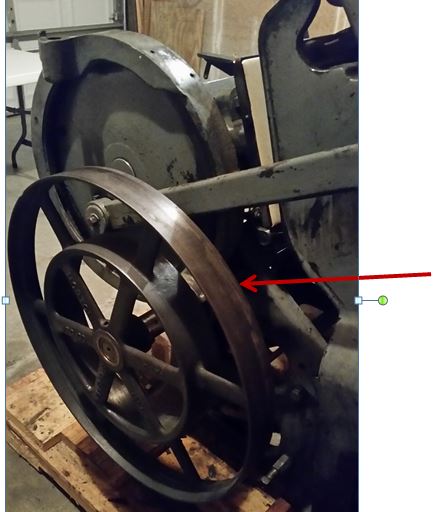
Remove wheel.JPG
check for a second set screw. remove it also if there, completely remove the set screws and you have an excellent point to apply penetrating oil. it may very well be, that some heat, like from whatever torch you can acquire, will be needed. drilling a dimple into center of the shaft will give a proper index for a puller that will fit .
What is it that necessitates the removal of the guard?
To me an equal question is why there is a unit of two pulleys of such different diameters. What mechanism needs that?
Once you’ve loosened any retainers, try a three-jaw puller.
ericm,
There is already a centre-drill hole in the end of the shaft, as far as I can tell from the photo… It might be a threaded hole, based on the following discussion…
parallel_imp,
I think that’s one pulley with a drum-clutch in the middle of it. You can see that the spokes of the larger pulley seem to terminate on the outside diameter of the smaller “pulley”. In fact, the smaller item isn’t even usable as a pulley. I think this is the remains of a Horton style clutch arrangement, but the inner bit with the shoes is missing. Some photos of a similar arrangement can be seen here:
http://www.practicalmachinist.com/vb/antique-machinery-history/identify-...
This is an important data point; with a Horton clutch, the pulley as seen in the photo would have been free-wheeling on the shaft, and the internal clutch mechanism would have been fixed to the shaft. Presumably a later owner decided to find some way to fix the loose pulley to the shaft. Originally the pulley would have been retained on the shaft with a cap bolted on to the end of the shaft. If the hole in the end of the shaft is threaded, that might at least provide some confirmation that this was the case for this press.
JDMunder,
If you finally do decide to go the three jaw puller route, remember to never pull on anything but the hub of the pulley. It doesn’t take much force to snap the spokes. Is there some bronze looking material between the pulley and the shaft? This looks like a non-standard setup, so beware of non-standard solutions taken to attach the pulley to the shaft — it might be pinned to the shaft, for example. Look for a taper pin or roll pin installed in a through-drilled hole.
Thank you for the information!
To answer the question why the pully and the need to remove the guard…
The press had a Kluge automatic feeder powered by a variable motor. We removed the feeder because I wanted to have more control while I’m learning the press and the feeder was just too much for the little bit of printing I’ll be doing.
Now the existing guard now lays against the gear and I don’t want to take a chance on damaging it.
Are you referring to the guard on the big gear visible in the photo?
Keelan
Thanks again for so much info. To answer your questions…
I went out and looked at the pulley again tonight and it is a Horton. There is bronze material in between the pulley and the hole at the end is threaded.
There is a set screw on the pulley, and the shaft does have what looks like a Allen set screw on the shaft.
Screw3.JPG
Center3.JPG
Perfect, thank you! So this confirms my suspicions.
Good news: the presence of bronze sleeve means that you’re not looking at something like a taper-fit or shrink fit. It tells me that minimal effort was made to convert from the Horton drive to a direct drive.
Not so good news: It looks like the whole mess is being held together with set screws. When dealing with shafts of this size, a set screw is rarely used alone. Normally a keyway is cut, and a key installed to resist the rotating forces. The set screw is usually used just to keep things from falling apart. When a set screw is used alone, being made of quite hard steel, it tends to booger up the shaft that it bears on. More often than not, when the screw becomes loose, the fix is to tighten it. Over time, this displaces metal up into the set-screw hole (see photo), and this metal will make removing the pulley quite difficult, especially if you don’t have a puller.
Remove the set screws and take a peek down the holes — do you see a ratty looking mess?
P1100985_zpsa1615e2f.jpg