Rouse Slug Cutter Functions
Ok, I admit up front I am a fool. Thinking that just because I knew something 45 years ago that I would remember it now was a mistake.
So, I bought a bunch of printing stuff really cheap ($5) but not all (or any?) was in as-new condition. In fact, maybe “not-cleaned-after-last-use-then-sitting-in-garage-for-10-years-condition” is more like it.
One item was a Rouse slug cutter, which I could have lived without but thought was way cool. So I took it apart and cleaned it really well and put it all back together. Really nice. (BTW-I know it is missing the return spring.)
What I failed to do - duh - was study it well prior to disassembly. I had no problem putting all the parts back where they belong (old machines are pretty easy to figure out in that sense.) My problem is with calibration and true positioning. And, as important, without that info I am not sure I can figure out what and why everything does what it should.
So, I am looking for a video or an verbal explanation of how to use this. Most of the process is obvious. But I don’t understand all of the measuring marks on all of the bars and such.
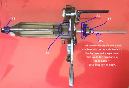
I took some photos of the various parts I don’t fully understand in detail. (I get the greater concepts.) I circled the areas I have questions about. So, I guess I need to know the function of each individual measuring spot and then how they all work together. Anyone who wants to take the time to answer would have my greatest appreciation, which is all I have left! (I know to flap the Rouse cover down on the left as well and why.)
I don’t know the names of all the individual parts so I numbered the parts to make it easier to correlate answers.
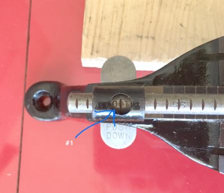
Notice 1 shows 100 but Image 2 is set at 5?
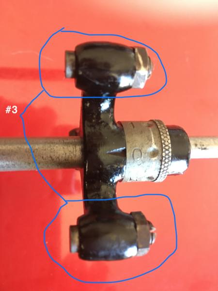
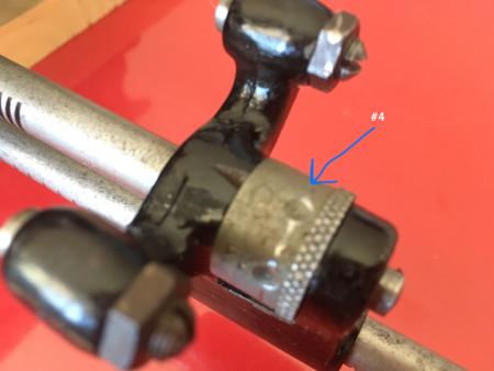
The do-dads in 3 are adjustable, but why and what do they do?
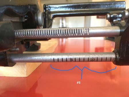
Images 4 and 5 seem to be used for feeding material in from the left vs the right? Or how do they relate to the measurements on the right of the cutter?
Not much to ask as far as typing a response, I know (!), but if you can tell me where to look to find the answers that would be good as well!
Thanks! Victor
RouseTop.jpg
Rouse1.jpg
Rouse2.jpg
Rouse3.jpg
Rouse4.jpg
Rouse5.jpg
Wow! Here goes nothing!!!!!!
It looks complete and correct.
#1. I can only assume that if you wanted to lubricate the spacing rod you could put a drop of oil in there. Reading the bar means nothing as far as I know. The “press down” wings below allow you to disengage the stops so that you can slide that bar back and forth to position it. Once you release the pressure, the bar should lock in place wherever you set it.
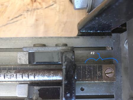
#2 is for setting the length you wish to cu. It is calibrated in picas, but there are half-pica stops as well between the hash marks. You visually align the broad back stop up to the hash (or half hash) of the length you desire and lock it in place. Then anything you slide-in up against it from the right side will chop off at the desired length.
#3 This is the head back stop to cutting different lengths that are fed into the cutter from the left (the original slide that we talked about is totally removed). This allows you to insert long lengths of strip material and simply push-and-chop and push-and-chop way faster than inserting each piece from the right side.
#4 I assume is for dialing in the length to points???? None of my cutters have that feature.
#5 Is simply the rod that holds the extension unit on.
The black flip-down piece is to provide a resting platform for the longer lengths.
That’s my humble attempt to try to explain in.
You will note that there are two tracks to use. I was always told to use the inner track for was 6pt thick material (because it gives more leverage for the cut) and the outer track (towards the operator) for the thinner 1 and 2pt material.
Rick
#1, to add to Rick’s explanation, the graduations on the round rod are for using it in the extended position, i.e. press on the wings, pull the rod out and put it in from the left side. The readings in the little round window are the measures from the cutter to the stop at the end of the rod which is hanging out in air.
The knurled adjustment #4, I believe, is indeed in points. This becomes very useful when trying to cut spacing material.it only needs 6pts for, as Rick indicated, the stops are positively set at 1/2 picas.
John Henry
Corroboration of the above with tiny variations,!
In reverse order,?
Your No.5 shot is the graduations in ems Pica, You possibly have, not yet, discovered the means to slide the right hand master register Bar backwards and forwards.?
In Your (Rouse Top,) shot look carefully, just to the left of the Handle appears a tiny plunger, almost certainly the positive click stop, for the Right Hand Cutting mechanism, but that is only the start,!
Your Rouse 3 circled together as 3/3 will be the mechanical adjustments for synchronising the front and rear cutting points, if and when, and after, the top and bottom cutting blades have been reground, the adjustments are quite critical.!
Next step would normally be, set the right hand adjustable, mechanism to 10 - 12 - 14, ems pica, via the *Plunger* read off in Your shot 5! (even Ems Pica always best for Settings with accurate furniture Resalite, Paxolin, Cornerstone Etc.) then with piece of said furniture, held against the fixed Blade of the Cutter, and the knurled adjuster, (shot 4 No..4) set to exactly (o) Zero, the Nut and Srcewdriver adjusters, are synchronised and adjusted to the Blade,! giving perfect Cuts, to exact length BUT with the option to, click stop DOWN in one point increments, IF the handset type is >spongy< ???
In Your Rouse Top, shot, above the No.3 is a Flip Down *auxiliary* support, useful when cutting Leads under the rear Blade in very thin form, i.e. 1 Point (if your are lucky enough) 1 &1/2 Point, or 2 Point. - - Good Luck Mick
**** Afterthought, is it just possible that against H 6,s stated reassembly procedure that the >Left Hand< calibrated ROD is actually upside down reading, and REVERSED end to end, ??? - Surely it should be reading, (according to the seen cutting position!!) more like 15/20 Ems rather than 100 UPSIDE/DOWN. ****
Self correction,?? Shot 2, indicates cutting exactly 9 ems Pica, racing certainty that with the rod reversed, will read in the >window< 9 Ems Pica.?
If the rod were reversed in #1 it would indeed read the extended measure of the materials being cut. It means nothing when used as pictured, rather you read directly off the graduated table.
John Henry
Wow! I am truly impressed. It was a bit of work to do the photos and number them and all, but the answers were very thorough and helpful!
I had NEVER thought of pulling the left rod out (the one reading in window #1) and reinserting it from the other direction, to make really long slugs; but it makes sense for the bigger presses (mine is just a 6 x 10.) Thus the 100. I knew the answer would be simple when explained. They never made things too complicated back then.
Mick - your explanation of how the adjustable stops in #3 would be used after the blade had been sharped, makes total sense. I could figure no reason to make them adjustable when I first reviewed it.
Mick - also, the explanation of pulling the rod (#1) out and turning it the other direction makes sense. It reads upside down as is, sure. But it is connected to the two sliders shown beside #2 and I could not disconnect it. So, when it is in the slot (#1) the numbers are upside down. But it isn’t removable for the two sliders shown in image #2. The rod isn’t welded to the sliders but there is a rivet that holds it in place and is not removable (I banged really hard on the whole thing before I figured THAT out.) But if the rod is pulled out and re-inserted from the other direction as Foolproof suggests, then the numbers on the rod become right-reading in the hole #1.
To all (and John Henry) - I had just never considered that the raw slugs would be fed from either direction - right or left. Of course, for those with larger presses it makes sense but for me it was confusing.
The fact that when a slug fed into it from the left read one length on the right hand scales and another on the left hand scales confused me and motivated me to make the post. I looked all over the internet and found nothing on the minor detail aspects of how these machines were used. Perhaps not everyone is as “simple” as me.
Mick - the explanation about how to reset the stop at #3 was very enlightening. I would never have come up with that.
I had figured out that the rotating scale at #4 was for fine-tuning, too, but exactly how it was used was getting past me so, again, your explanations helped.
Rick - thanks for the inner track/outer track info. I had guessed at that, based on how the slugs fit in, but I was not positive. This nails it.
Guys, this saved me a LOT of messing around and cutting down slugs to see what happened. Now, I will play around with it a bit to finalize the settings and make some slugs and leads .the size I need. And then I will move on to renewing the miter cutter that I also got at the same time in the $5 purchase of a stack of stuff. I may be back with more question in about a year!
H 6 thank you for the feedback on the humble efforts, You will probable find that the calibrated rod that seems to be reversed, is in actual fact secured in the correct plane with tiny grub screw, rather than a *rivet* as you describe, which would be synonymous with the Badly pitted inner end, which should be the outer end, as in Your shot, Rouse 2, appears to be registering nothing against nothing.!
Normally would be expected to be the outer/unused section, that gets No T.L.C. or even a wipe with the oily rag. Not even the odd shot of oil, from the .38 Calibre, Smith and Wesson OIL CAN.!!!
Print shops Large or Small with chemical laden atmosphere, are fairly notorious for inviting (almost overnight) rust or sweating on cold steel/iron.
My own Typecasting M/c. Cropper Platen, and Lathe attract their fair share, but can be kept at bay, up to a point via the Oily Blanket(s) thrown over at night, or a few *Squirts* of clear lacquer, now and then, on the moving parts that are Not painted,. Looks >tatty< but works well.
Thanks. Mick.
When you get into the miter cutter, be very aware that the handle is intentionally loose and “sloppy.”Do not knock yourself out trying to tighten it. There is an “art” to using the miter cutter and we’ll leave that for another day once you get into it.
Rick
Thanks again. I will look for the “grub” screw. I assume a “grub” screw is the same as a “set screw,” as can be seen in the bottom section of my shot #2. That set screw holds in place the handle that move the rod that can be seen in shot #5. I will look for one holding in the stop mechanism shown near the 5 in shot #2. Given that that rod is meant to be pulled out and used from the other direction I can see what you mean about neglect. There are not many needs for slugs that long I would imagine.
Rick - I won’t be getting to the miter for a long time since it is in such bad shape. I may need to sand blast it down to raw metal and then repaint to whole thing it is so rusty. San blasting isn’t my thing so I will be putting that off for quite a while I believe. Too bad my neighbor with a sand blaster moved about two years ago!
But I will remember your advice when the time comes. Part of this personal project (assuming I live long enough) is to become familiar with all the small machine so I hope I get time to red it but I want to spend some time actually printing and not just renovating equipment!
Thanks, again, y’all.
Hunter 6 - Victor