Removal of oscillator roller bearing
Hi C&P enthusiasts
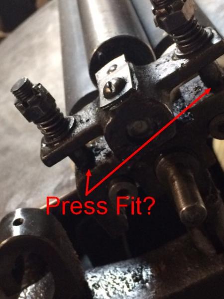
I want to disassemble the roller rider bearings on my C+P 8x12 new style, but can’t get the things off. They are situated on top of the double saddle bearing and appear to be screwed into the saddle north and south of the oil holes! As there are no weld marks, I kind of think the bolts may have been press fit into their own holes. The bolts holding the bearing in place do not go all the way through the saddle bearing, so it’s not like they’re riveted in place.
I would prefer to not have to cut these off. Another BPer needs this oscillator far more than I do.
I have included a photo.
Best,
Mike Moore
LetterKraft Press
OscillatorBearing.jpg
2 possibilities, both of which may be irrelevant, (Apologies if so)
First option if as it appears that You can reveal some plain shank (un-threaded portion) of the bolts, although appearing to terminate in a blind hole, Lock 2 nuts together to act, as ONE and as a normal hexagon headed bolt, unscrew the Whole as a normal bolt.
OR
Option 2 Purchase >Cam-lock style Stud Extractor>
Simple as, fits onto a normal 3/8” or 1/2” drive normal wrench extension/reversible ratchet spanner, slips over the stud/stub, the eccentric serrated cam locks onto the stud and merely winds it/them OUT.!!
Again Apologies for rubbish. - Good Luck Mick.
hard to see, but, don’t those plates raise up against the springs? then kinda slide the whole roller out?. these are made to be removed as needed, so it can’t be too difficult.
Those are probably threaded studs screwed into the roller saddles. You might just try a pair of vise grips on the studs (gently, gripping close to the saddles) after you remove the nuts, springs, and rider roller journals. Or at the least clean carefully around them where the go into the saddles and see if you can see the ends of threads to indicate that is how they are attached.
Bob
I tried unscrewing them with channel lock pliers and then vise grips, and nothing. But I am going to try this again after completely disassembling the bearing and that way I can stabilize the saddle and really apply some persuasion. Also as you can see from the pic, I need some better lighting on the subject.
Fortunately the beneficiary of this device has the services of an engineer with a 3D printer — how cool is that? I don’t see a problem installing it at the other end….
So as long as I can get it off of there without breaking anything, I’m going to call this one solved!
Thanks everyone for your comments.
Mike
I would remove those locking cotter pins and then unscrew the nuts before trying to remove the whole stud.And the middle screw? Small, sequential moves give a better understanding.
ericm is quite right that these were designed to be removed easily. I bought a different style of rider when I was a young C&P owner , and I thought it was positioned as yours, between the top two rollers. Nope. It went over the bottom two, but before I realized that, I had sawn off the lifting stud from the roller saddle.
So I’m looking at the saddle on our C&P Craftsman without the rider roller and those bolts look like the threads go down into the saddle. I don’t know if yours are similar or not. But the rider roller and bearing assembly have been removed and the bolts are still there so it may not be necessary to remove the bolts to do what you want to do. Does the prospective new owner need the bolts or does He/She already have them on their press? Why remove bolts you don’t need to? If this is irrelevant to you my appologies.
Bruce
CP saddle pic.jpg
Hi Briarpress,
I want to thank everyone for comments, all were helpful to get this oscillator on its way. ‘Bruce cpd’ your photo brought back some fond memories of my dad’s press, as this was the arrangement he had that one time we needed the oscillator for a large cut that took an ungodly amount of opaque white ink.
To close this thread let me tell you what I did to remove the oscillator bearing. Whoever initially mounted this set really, really didn’t want it to come out (looking at you, Lance Williams).
The oscillator bearing assembly was screwed into the double saddle form roller bearing with a quarter inch machine threaded bolt and seated well with some kind of thread lock.
Then, there were (initially invisible) 1/16” holes drilled through the inside surface of the saddle, right through the bolt, where pins were press-fit into the holes, keeping the bolts fast. I did not understand initially there were side pins in place, and that’s why the bolts would not come loose without a lot of Archimedic persuasion. At the other end of this effort, the recipients of the oscillator are more than capable of reproducing this firmament, so I was not too worried that the bolts had to be basically shredded to remove them. I included them in the crate for good luck! Also I traded my crate-building skills for chocolate - you can’t go wrong with that sort of kindness! Gotta love Briarpress!
Mike Moore
Letterkraft Press
Union, Kentucky
Sounds like you possess some sweet barter skills.
(I couldn’t help making a light hearted joke in reference to your chocolate trade- but at least my humor wasn’t… Dark!)