Farley proof press
Hi there.
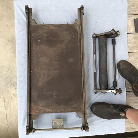
Hoping to get this one time abused Farley proof press up and running. Anyone familiar with the model? Looks like an older style type high mechanism as opposed to the models with the adjustment on the carriage. I was advised it’s been welded accurately - proof will be in the pudding … or the bin. Anyways, any info appreciated on this press and it’s carriage bearings sizes - are they a generic imperial size I can purchase over the counter?
thanks in advance.
Matt
The Tilbury Press

farley 1.jpg
Farley 2.jpg
Farley 3.jpg
G`Day Sport, Yes standard imperial Bearings, albeit with one small proviso, (usually) with quite narrow format to match the width of the bearer rails, and without dust covers, shields, or oil or grease access, just a couple of squirts of oil.
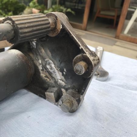
You will probably/hopefully find that the stubs/axis for the bearings are actually *Eccentric* with screwdriver slots and locking nuts. ! !
You will probably find that the transverse rod/tie bar seen in
shot 1, is in fact the means to crank the bearer rails down onto impression and Vice Versa.
Farley,s were made in Croydon Surrey U K. sadly long gone.
With the measurements of the stub spindles (minus the rust of course) the depth of the bearer rails, and with the welded up section (even the whole carriage presented to Your bearing supplies) they should be able to supply the correct bearings.
Apologies for stating the obvious, but may be a *yardstick* for starters.
IF all else fails we own and use a similar proof press, although NOT a Farley, ! could measure and quote the bearing arrangements, at least for cross reference purposes.
Good luck. Mick.
On a personal note, may have to get *Arthur Dunger* - Hoges, to take issue with You regarding Them legs, No Strides, and bringing L/press in Oz into disrepute.
Non intended. Whingeing Pom. U.K.
Happy Xmas.
I have exactly this model, right up to the broken and brazed mechanism.
I think it’s a model 1.
As Mick Hopper notes, the grey handle in the front of picture 1 controls the impression or type height. You push it down or pull it up to run a proof or just skate over the type. You can adjust the runners level and height with the 4 lock nut set screws on the 4 corners and I think there’s something underneath to make further adjustments. (I’ve only done mine once and I think I should have used the underneath bit).
They could come with a tray for ink rollers, etc which screwed into one end AND there was a paper feed tray which could be hung over the handle (see below). There’s no gripper but you can make one (see below).
Niether image is mine so all credit to the originator
2.png
1.png
Very interesting! I am baffled about the adjustment/setting of the eccentric lower bearings. I took mine apart to clean without careful note. One side plain, one with eccentric centre (cam) with lock not and centre screw adjustment. I have replaced 4 bearings: exact match, available new Sydney supplier
Hi Simon, Mick and Richard.
Thanks for you interest.
I noticed the bar on the far right with the rubber stoppers was assembled incorrectly. It currently is in holes where studs and bearings sit. Seems is should be at the very base so it runs under the bed (my interpretation anyhows).
It took a fair while to tap the assembly apart and when put back together as above it was soon proved that the welding was not accurate as bar with the rubber stoppers sat skewed by 10/12mm one end.
So probably welded together on the bench rather than assembled on press, held with clamps, then welded etc.
I’m now A) investigating getting replacements cast off undamaged pieces (though shrinkage is an issue) or B) complete fabrication of each of these sides. Do you believe they are the one casting used both sides?
So down tools and research downed for Christmas…. and enjoy the shorts weather. Ha ha.
Matt
Hello Matt,
Wouldn’t it be safer and easier to see if a good machine shop can make you those parts? If you can supply someone with accurate drawings, it shouldn’t be difficult I suppose. And maybe less expensive and risky than getting something cast?
Update. Turns out this has been poorly welded and will probably need fresh sides produced/machined - I have parked this little task fir the short term. Thanks.
Yes, that would throw everything out. IN THEORY though, you’d only need mild steel plates for the outside which you could get laser cut out of 10mm plate. Then just add the offsets if required.
I have acquired the same model. There is a catalogue page on Flickr which suggests this is a Farley Model 2 with “moving bearers—lever operated and adjustable”.
I posted here:
http://www.briarpress.org/51935
before I saw your post. As you can see from my post, the impression lever is jammed and I expect it should flip freely between the two settings.
Incidentally, I thought the two settings are to cope with type on a galley and type not on a galley but I guess you could use it for impression on and off if you want to return the impression roller to your start end, which you would do if you set up grippers or a frisket arrangement.
Does your impression lever move easily between the two positions (and the bearers move up/down freely?
I expect I will have to soak mine in WD40 to loosen things up.
I hope you have sorted out your broken side arm issue.
Roger
You can 3D print the patterns for casting and allowance included for shrinkage and machining.
Where in Oz are ya?