SP-15 needs your expert help!
I will be the first to admit, I have a serious mechanical-ability deficit. I don’t work well off diagrams and instruction sheets; for example, my husband used to have to read the instructions for the board games we played with our kids first, and then explain them to me (even Hi-Ho-Cherrio! was beyond me). It’s that bad.
So there may be simple explanations here (or not). I’m trying to get this behemoth up and running, and have run into some snags. I know this press worked before I received it! (Pardon any misapplied terminology.) Here is what I see:
1. The motor runs, the cylinder turns, but the ink drum doesn’t turn and go back and forth, and the form rollers don’t turn either.
The worm and crescent was replaced just before I bought this press (which is why I have ever even heard the term “worm and crescent”, not that I know what it is!) so — what else could be causing this and how can I fix it?
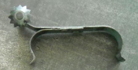
2. The cute lil’ part in the photo that has the star-shaped tip fell out as I was turning the crank to see if it worked. What is it, what does it do and where does it go? I don’t find it in the manual.
3. Do the form rollers look as though they are on correctly? The manual says they can be raised and lowered by turning the black knobs, but that doesn’t happen.
4. The manual shows some nylon bearings on something near the form rollers, but this press did not come with any nylon bearings. What part would they be for?
(4a. This was a school-system press, so might it differ in some ways from SP-15s for general use? Just wondering.)
5. When I push the trip lever, what should I see? Shouldn’t the whole roller carriage mechanism travel all the way down to the end in either mode? It stops after half a crank on trip.
(The 4 that I have taken classes on has a very obvious part on the outside that goes over or under another part, depending on whether you are in trip or print, and the carriage travels all the way down, so this is somewhat disconcerting.)
6. I did check the archives here, and I also have called several folks/shops in my local area (Mpls/St. Paul) who appear on the Vandercook census as having an SP-15, but have not found a local expert who can help me. I have someone who has used other Vandercooks coming to take a look in a couple of weeks, but …
7. …if you are in my area and have expertise in fixing these presses, will you just come over and fix this dang thing for me? I will cross your palm with silver, beer, pizza—you name the currency. Once I see for myself how it works, minus the intermediary of an instruction manual, I’ll be good to go. (I think.)
Many thanks!

DSCN0229.jpg
DSCN0230.jpg
DSCN0228.jpg
DSCN0231.jpg
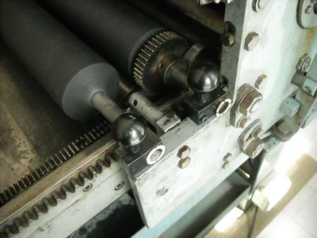
The rollers are in the up position. There is a lever that lowers them to working position.
To adjust the form rollers, you have to loosen the lock screw first.
You have Nyliners in place, you can see the little white flanges at the end of the roller shaft. I think the flanges should be on the inner side of the roller block. I don’t see the end bolts either, that keep the rollers from shifting between the roller blocks.
The starwheel clips into place behind the rollers, on the two rods near the cylinder. It holds the sheet near the clinder, and there are normally two of them. You may see the other in place.
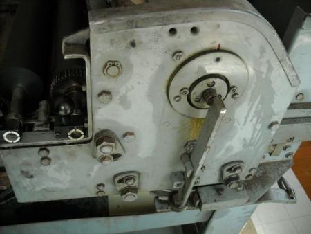
The cylinder will be lowered, on print, at the feedboard. Does it go forward normally on print, but stop on trip? Then the trip assembly is probably stuck, possibly from one or two broken trip springs. Or are the nylon wheels present on the side of the press? There are four, two on each side, and are part of the trip mechanism.
First thing I notice is that the roller cores are in backwards. Also the roller blocks should be in so that the Allen head bolts face outward.
Do you have the end bolts?
Daniel Morris
The Arm Letterpress
Brooklyn, NY
Thank you both! Folks, keep those cards and letters coming.
• There are no nylon wheels anywhere on this press. The trip mechanism must be missing something. Yes, the carriage goes all the way forward on print but stops on trip. Sigh.
• Starwheel has now rejoined its previously unseen mate.
• End bolts?!? I don’t think I have any such. Are they just regular bolts that go on the ends of the cores?
• Rollers on backwards?—par for the course—I tend to do everything backwards (and in high heels) first. I’ll try again.
p.s. This group was invaluable throughout the whole YEAR it took for me to figure out how to repair my simple little Sigwalt No. 5, and I imagine this press will take even longer to sort out; to compensate for my many deficits, Nature gave me the persistence of a pit bull, so I hope you will all be patient with me.
If you position the cylinder over the bed, then come back and flip the trip/print lever back and forth, you will see a rod popping out of the side of the press (leave the lever on “print” when you are done). Just to the right of the rod is where one of the white nylon wheels should be, and another on the far side of the press. They rotate on a post, and are held on by retaing clips. Then there should be a second set of wheels down ay the end of the bed. If there are no wheels, are their posts there?
These wheels activate the trip/print mechanism: into the trip position at the end of the bed, and to the print position as the cylinder returns to the feedboard.
White nylon wheels found! They aren’t white any more, and I am so easily misled. But there they are. Trip rod pops out just as you said, p_i.
Now—shouldn’t I be able to crank the ink roller, etc. all the way to the end of the bed in either mode? as I can on the 4? It looks as though the rod stops the forward motion.
It isn’t the ink roller you are cranking, it is the cylinder assembly. And I’d bet that if you cranked a bit harder you’d find that it will go the whole way. On trip the SP-15 requires a bit of a bump to get it started. If your press hasn’t been oiled in ages then it could need quite a bit of force.
There are a lot of things in that roller assembly that jump out as being assembled incorrectly. Do you have a manual for your press? You can get one from NA Graphics.
Daniel Morris
The Arm Letterpress
Brooklyn, NY
n/a
Hi Daniel, Yes, I have two manuals, in fact. Both look like Sanskrit, although I know they were written in the finest mid-20th-century industrial English.
I’ll try again on that roller assembly. I will post some new pix here after I do my nightly what-the-hell-is-THIS session.
Also, thanks for fixing my terminology. Right now, all these parts look alike to me, but soon they will become my dear, individual friends, with all their greasy little quirks, and I will know their names and affectionately call them thereby.
Devils Tail, I am armed with an oil can and ready to fire. Will post updates.
Thank you so much!
One tip I will point out is that on the metal roller cores the gear goes on the side that has the little flat spot near where the rubber starts. The allen head set screw in the back roller’s gear should be tightened on that flat spot.
Dan
Yes it looks like the toothed metal gear on your back rubber roller is on the wrong end of the roller shaft - that’s why the roller shaft (core) is protruding too far out on the operator’s side. You need to take it off, put it on the other end on the flat spot Dan mentioned and then flip the whole roller.
Have a look at the vandercook pool on flickr - a guy called interobang(?) did a nice sequence of roller preparation and installation.
good luck
John,
I’m glad you pointed that out. Here are those photos.
http://www.flickr.com/photos/interrobang918/sets/72157594510327158/
Dan
I bring this progress/no-progress report after a weekend littered with Allen wrenches and oil cans:
• I’ve made another attempt at putting the rollers on—better?
• The ink roller still doesn’t turn or travel from side to side. What exactly makes this happen—is it just contact between the cylinder and the rollers, or is there something else I should be checking?
• Despite soaking in oil for two days, the press still stops dead on trip after half a crank, so I think it must be something gone haywire somewhere and not just that it’s stuck.
• The holes in the flat side of the ink roller are on the off-side on my press, but it looks in the manual as though they go on the operator side—does this matter? Should I flip it?
• Adding to the mystery, a small spring appeared from nowhere, and I can’t figure out where it came from.
Your ideas always welcomed with gratitude!
DSCN0223_2.jpg
DSCN0226.jpg
DSCN0224.jpg
DSCN0223.jpg
DSCN0222.jpg
Clothdog
Are you sure these form cores are correct for the SP15? something is not quite right here.
Gerald
http://BielerPress.blogspot.com
cloth dog, its good practice to get the terminology of parts correct here if people are going to help you on-line - each part is labelled in the manual and it will help us to help you.
I’ve labelled some parts in the meantime on the photos below:
• you say the “ink roller” doesn’t turn or move side to side - I assume you mean the ink drum vibrator assembly? This assembly contains the mechanism called the worm and crescent which you say has been replaced. It sounds like the crescent holder has been screwed down too tight and so the crescent is stuck against the worm. Sheet 254 in the manual tells you how to set it correctly ie. - loosen the set screw, screw in the crescent holder until it tightens, then back off (unscrew) about 3/4 of a turn. Retighten set screw. Your ink drum vibrator assembly should now move freely if you try and rotate it with your hand. In order for it to ink you have to release the catch on the far side of the assembly and then lower it onto the form rollers using the lever on the operator’s side. (Hold the inner lever when you release the catch or it will drop with a clang).
• The whole cylinder assembly (rider roller, form rollers, ink drum vibrator and cylinder etc.) doesn’t travel the length of the bed on trip? A frequent issue with the SP series would appear to be broken trip springs. When you advance the cylinder assembly down the bed on trip the cylinder is literally ‘tripped’ - it is lifted within the whole cylinder assembly so that it doesn’t receive ink from the type sitting on the bed. If the trip springs are broken then the cylinder will not lift and the trip assembly may become stuck with the trip arms in the down position. This may be the reason why you cannot move the cylinder assembly the whole length on trip - the trip assembly cannot rotate when it hits the two trip rods which protrude from the bed frame.
There is a diagram of the trip assembly on sheet 248 which shows a coiled trip spring. However my guess is you have an sp15 variant that uses a flat spring - see
http://www.flickr.com/photos/8286330@N03/3265698377/in/set-7215760021842...
(Fritz - do we know whether the flat spring variant was a feature of older sp15s - ie. did Vandercook modify it to a coiled spring?)
• In the other photo below i’ve moved my cylinder assembly along the bed to reveal the ink drum which is attached to the motor by a drive belt and rotates when the machine is switched on. In order to move the cylinder assembly along the bed the cylinder assembly pushes the ink drum down as it travels over a flat plate on the operator’s side of the ink drum. Does your ink drum bounce up and down if you apply pressure to it? The spring you have shown is one of a pair which enables the ink drum to bounce up and down - if you have lost a spring it may be stuck.
• could you measure the length of your form rollers - the steel core tip to tip should be approx 21.5 inches.
If the press came from a school in all probability it has been neglected and parts may be missing. Many parts are still available however so don’t lose heart - potentially you have a great little machine. You may have to consider this a restoration project before you get to print but in the process you will get to know the press really well!
good luck!
ink drum vibrator shot
ink drum
Hi John, Helen Ingham here, we were in touch a couple of years ago when I attempted to set up a group on Myspace (but get too busy at work to continue with it!). Anyway, you probably already know this, but there is a very good flatbed proofing press expert in Brighton. His name is Basil Head and he services all the machines I’ve used at the colleges where I work. He’s also given me plenty of advice over the phone. If you need his number it’s 01273 503791.
Good Luck,
Helen
Hello Helen - still expecting you to turn up in your leathers on a Brighton run one day! Thanks for this - the sp15 seems to be running sweetly but i might just ask Basil to fine tune it one day!
all the best
john
The coil trip spring on the SP series came first. Flat spring started with s.n. 23925.
That’s a useful set of photos you put up there, John.
More valuable clues and immensely helpful photos. Thank you so much for taking the time to help. I will use all of the above info in tomorrow evening’s session.
Meanwhile:
• I’ve measured the cores and they are 21.5” across—these are brand new rollers. So I must still be doing something wrong if the setup looks odd—but what could it be? (I don’t have the end bolts, must get some…)
• The serial number of this press is 22297, so it must have the coiled trip springs, and I bet this loose spring is one of them.
• I am sorry for mangling the names of parts. It is not for lack of effort…just utter confusion upon entering the SP-15 thicket for the first time. Yes—I did mean the ink drum vibrator assembly is what doesn’t move. I’ll go at it again, armed with all this new info.
That loose spring is not the trip spring. The coil trip springs are compression springs (which push things apart), and that spring with the hooks is an extension spring (which pulls things together).
Parallel is right - the spring is an extension spring. I think it is the part labelled BRS-I spring on sheet 247, you should have 2 of them and they suspend the unit containing the motor and the ink drum assembly to the bed frame. They enable the ink drum to bounce back by pulling the whole unit back up after the cylinder assembly has pushed it down.
Clothdog - advance your cylinder assembly to the end of the bed. Push down on one end of the ink drum and then the other - both ends should feel bouncy - let us know what you find.
Here is the latest in the SP-15 saga, so far this evening:
• The spring indeed seems to be the second of the pair that suspends the ink drum. My current frustration with that is that there’s so little room to maneuver between the inside of the press and where the spring goes, making it impossible (so far, after 7,234 tries) to re-attach both ends of the spring. Perhaps there is a special spring-hooking tool I have never heard of that can fit up the side of the press?
I can hook the top OR bottom of the spring, but not both. It has a lot of tension, and the problem is keeping the already-hooked side hooked while trying to pull the other hook toward its destination, with no room for even a finger. (The photo makes it look much roomier than it is.)
I even took off the slotted motor cover to see if that gave better access to the spring, but it doesn’t. I did, however, find a ton of long hair and grease! eeewww! I cleaned it up, imagining San Francisco high school students in the ’70s getting their freak flags ripped out as they bent over the humming press in shop class. ooowww!
• I tinkered with the crescent holder per instructions, and the ink drum vibrator assembly rotates just fine on its axis when moved by hand. What it doesn’t do is travel from side to side by itself, as it should to spread ink evenly (right?). When the motor is on, it just sits there doing nothing.
I am worried that it might be on backwards—on sheet 286 the holes are on the right side, but on mine, the holes are on the left side.
And I still don’t understand what would make it travel if it *were* working—is it simply a gear-like action from the ink drum, to the form rollers, to the ink drum vibrator assembly? Or is there something else I can’t see? Even in their lowest position, the form rollers are not touching the ink drum, so perhaps that’s part of the problem?
Many thanks!
Spring.jpg
What’s the diameter of your form rollers? They should be 3 inches. On a Vandercook the roller diameter is pretty critical to having everything in complete contact, though the oscillator and idlers should just rest on the forms. The forms have to be set low enough to contact the drum and the type — have you set them with a gauge?
A simple way to install an extension spring is to pass some heavy string through one hook, put the other hook where it is supposed to be, and pull on the string to extend the spring. It may take another tool to guide the hook into the other hole, maybe a second set of hands.
The rear (geared) form roller must contact the ink drum for the inking system to work. Drum drives rear form which drives oscillating roller which drives front form roller, all by friction. Then when travelling down the bed the gear on the rear roiller provides the power. Again, the form rollers must be lowered to operating position using the lever (and raised again when not in use) and the distributor rollers lowered as well..
Very worn worms or crescents may allow the osciillating roller to turn but not oscillate much, but not good ones. (Broken points may just align in one section of the worm for a very slight oscillation.) Normally they are placed on the operator side of the press for ease of access. It will work in either position.
Ohhhhhhhhhhh!
Three inches, you say!
Mine are only 2.5 inches. That might explain a whole lot.
A string to hook a spring!
I would not have thought of that in a trillion years.
Hearts to you!
Hold on, those rollers can’t be 1/2” under-size. In photo 224, they are level with the gear; a 1/4” difference would be visible. Unless the gear is also wrong, they must be nearer to correct diameter.
It is true that even a 1/16” undersize roller may not be adjustable to type-height on the gear end. But I think something else is going on here. Or things.
I actually looked at this press when it was in SF (different set of rollers apparently), and we had no problem inking up, adjusting rollers, and pullling a test impression then.
cloth dog - could you take a series of photos of all the rollers associated with the cylinder assembly all in position. Then lower the ink drum vibrator and rider so that they rest on the form rollers and take some more photos.
Back to the worm and crescent - the manual says back off 3/4 of a turn, try a couple of turns and then relock the set screw - does it travel back and forth then?
P-I, these form rollers were sent straight to me from the roller folks after the press was shipped, so they are indeed different rollers than you would have seen. I know this press worked fine in SF, and I know it will work again, which is why I am not discouraged…well, maybe just a little!
I will take pix of all the rollers in all positions this p.m. and also make another (gentle) assault on the w-and-c, adhering to my motto: If at first you don’t fricassee, fry, fry a hen.
P.S. On the topic of springs, my son recommends this video (and I will second that, when I stop laughing):
http://www.youtube.com/watch?v=ngBNklagsHQ
Here is a photo of one of the form rollers with a yardstick. These rollers definitely are smaller than 3 inches!
The edge of the gear just protrudes around the edge of the roller it is on—is that how it should fit? I don’t know why the gear would fit when the rollers are clearly too small. Curioser and curioser!
I’ll get the other photos when camera recharges.
roller2.jpg
SP-15 rollers are 2.500” in diameter. They are typically made up to .030” larger in diameter to allow for initial shrinkage as all rollers will shrink as they age. To measure the diameter with inaccurate devices such as shown, place both rollers on a flat surface, lay a flat edge from one roller to the other, then measure the distance from the surface top to the bottom of the straight edge. If under 2.500 inches, then that’s where a problem may exist if the diameter is off by as little as 1/4 inch. Correct diameter is absolutely important.
It does sound like the cylinder trip spring, BRS-2 is broken or missing, and I do not have any in stock, but it is a simple spring that we could have made easily. It was taken out of inventory in 1974. What bothers me is that if this press operated smoothly in the equipment dealer’s shop in San Francisco, then I doubt that this is the cause of the cylinder stopping.
The crescent assembly has to be adjusted as mentioned, and it is easy to remove once the set screw is loosened and the crescent holder is backed of—it may have a broken tip, or stem or ?? How about a photo of the disassembled crescent and holder?
Both roller cores should have the same orientation with the flat spots for the roller gear set screws on the non operator side of the press, and the end bearing screws, while not a controlling issue, should be replaces, and as Eric pointed out, Nyliner flanges to the inside.
The roller adjustng stems with the black plastic knob are held in position with a set screw on the side of the bearing block, and this screw has to be loosened each time the stem is adjusted and then retightened. I do a thriving business of selling new knobs to people who think that channel locks or vise grips are how these stems are adjusted.
I second with strong emphasis the use of part numbers and part names. And since manuals are available, there is no reason one of those is not used and available for these discussions to avoid confusion and waste of time.
Fritz/NA Graphics
Another comment or two. Basil Head was the representative for the Vandercook Co. in Great Britain and I have a file folder on work Basil did for Vandercook back in the 60s and 70s, and he still obtains parts from us.
Second, it does appear that the vibrating ink drum is in the press backwards—follow the pictures in the manual.
Fritz
Back to the worm and crescent within the vibrating ink drum - make sure this is lubricated liberally with vaseline to avoid wear on the crescent.
Thank you for the advice and information. I am going to take more pix and work on the crescent and holder tomorrow when I’ll have some help; I get nervous taking things apart by myself for the first time because of the possibility I won’t be able to get them back together correctly. (Yes, even with a manual and photos.)
An update on my SP-15 saga for all you kind folks who have given me a helping hand here: The best news! Dave Seat is coming through my town in July, bringing his wonderful Tennessee accent and knowledge of presses, and he is going to come over and (we hope) repair this puppy.
I am delighted. Relieved. Thrilled!