Heidelberg Windmill - disassembling gripper unit.
I’m making die-cutting on my Windmill with lay gage registration on because I have a problem that 2 grippers give 2 different registration. Sometimes I have to make a job where I can’t use gage registration. And today when I’ve failed again to use the gages I’ve made a decision to fix this problem.
Noticed that there is ~1,5 mm gap of the gripper carrier relative to the gripper shaft. I’ve was “hoping” that the problem is with the large gear GT1437 because it holds 2 revolutions of small gear. Was thinking that some gear teeth are worn. Took off the cover and yeah found a little gap between small and large gear. This problem can be solved by adding a washer below large gear so that it will become higher and thus make better connection to small one. But this found gap is so small comparing to another one found. Seems that I got ruined bearing O23 because after taking off the cover that is holding one side of the main shaft the gap became actually very evident. When the cover is off now the gap is not only in horizontal plane but also in vertical.
Trying to get to bearing took me 3 hours with no luck. Parts manual shows the greaper carrier alone so I was sure that I can take the carrie off.. Ha! no luck.. Then I tried to start from below with the same result. Came here to search for the issues that might someone had before and found 2 topics - http://www.briarpress.org/31045 and http://www.briarpress.org/26312
After reading those I understood that I should continue with removing gripper carrier (from above). But damn I can’t do this at all. Spent 1,5 hours and seems not even a micron of progress. It just stucked. No pin is there. I got confused when in the last topic a man just hit few times with rubber mullet and the gripper carrier moved on the shaft. How? What’s the secret? Anyone please tell me how to take this carrie off.
please don’t guide me to “Hedielberg specialist” since in my country I have none of them - those who are deal only with modern presses not this ancient ones.
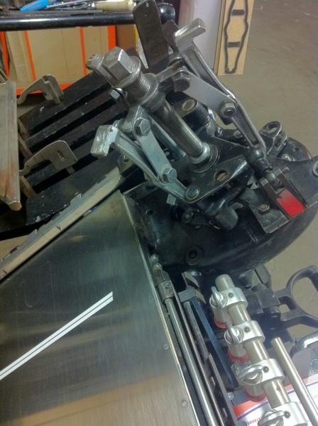
Attached actual picture of my GT.
Thnak You for help!
Above.JPG
I watched this operation done by the trained Heidelberg Specialist on my neighbours 10x15, not on a GT. ( $75 per hour )
The odd thing he did was that when he was at the stage like in your picture, he tied down the gripper holder and the gear puller with a rope. He said that when they POP free, sometimes they would fly off the machine. In our case it was a quiet pop, no flying parts and tools. But I guess in some cases the parts can be seized.
Once I had to remove the air pump crank from it’s shaft. Huh … if you wanted to see a grown man cry … LOL. Patience, Liquid Wrench, Dead Blow hammer and HEAT helps. In the time between breakfast and lunch it got unstuck and the gear puller started to work after lunch.
PS
I don’t think that gear wear has anything to do with gripper positioning. Trough a good part of their revolution the grippers can be moved a bit by hand. That is a normal gear play. But when they reach their commercial register position, a cam inside the head locks it in position for that moment. When the platen is closed, you should not be able to jiggle the gripper, the one sticking up in the air.
Louie
http://eagleprint.ca
the gripper bar assembly is on a tapered shaft. After installing puller you must hit the threader(puller) with a large hammer. The force will jar free the gripper assembly and you can can then re-align. The gear thing is a red herring. Most probably the gripper(s) had been in a jam and moved of center slightly.
You may already have hinted at the answer to your own question,!!!
I.E. even when you have the puller under extreme pressure, frequently a fairly heavy blow with a Copper or Brass Hammer, on the head of the puller cracks/releases the stubborn part, short sharp shock usually does the trick.!!
On OUR British Thompson Platen, (Like the Heidelberg) and EVEN with An Hydraulic Puller rated at 10 Tons Pull/Pressure it still needs one or two Blows to release the 2 parts, (on the Thompson different parts, but even more pressure required???)
BUT
as the Good Buddy above implies, your diagnosis may not be correct, perhaps more investigation,? is required, before further drastic measures, and as above, restraint of some kind, and possibly MARK the position(s) of the meshing Teeth for reassembly.*****
> Usually via one Male Tooth and Two Female teeth, self explanatory, hopefully,!! <
either with Tippex/Paint or Printing ink, or best of all (foolproof) with a tiny Hard Steel pin punch, ONE dot on the chosen Male Tooth and One dot each, on the two corresponding Female teeth.
Good Luck.
Mick on Monotype, I was tempted to ask you to elaborate on the “one Male Tooth and Two Female teeth” thing, but I Googled it. I looked at the images and now it is all clear … LOL … I left “filter images” unchecked!
Anyway, talking of images. Here are two pictures I took just now on this subject.
MaMaDx, first you have to check if your grippers are not smashed and bent. On the 10x15 BOTH gripper bars should be PARALLEL to the platen and 6 points away from the cast iron surface. That is a 6pt. lead slug under the gripper shown in the picture. Any difference in these values between the two grippers, will show up as a consistent miss-registration on every second sheet.
I smashed my gripper once. One suppose to use a long steel pipe slid over the gripper holder to adjust ( bend ) it back to it’s original shape. I did not had a long steel pipe, so I used a 0.5” carriage bolt, 2” long with a nut as a spreader tool. It worked quite well and I did not had to remove the gripper bars either and it was easy to see what was I doing. Of course it was a gut wrenching experience.
I think, that I should mention it here, that what I did, might not work for you. I am just sharing my experiences and I do not want to be liable to any damage to your or any other person’s press. I am not a press mechanic and these are not instructions for anyone to use!
Louie
http://eagleprint.ca
six_point.JPG
spreader_bolt.JPG
By the way, I use this. I value it more than my press. Except the envelopes, I do everything on hairline register. This one is as old as my Heidelberg, but new ones are available from Boxcar Press.
Louie
http://eagleprint.ca
my swing away lay gauge
Boxcar swing away lay gauge
Louie, and on behalf of MaMaDx, Thank you, for the nod, apologies for my seemingly crude metaphor, but it does seem to be sort of universal.!!
Yes you are correct with your D.I.Y. Gripper Arm straightening method, Heidelberg Field Engineers do actually perform the operation with a Service tool, which is a bar about 36” or 1 Metre long, with a specific *Boss* at the working end to fit over the 2 stubs, that normally carry the gripper fingers, and basically Hand and Brain!, crank the stubs back to the true alignment position x 2.
The following has been posted several times in the past, on B.P. The factory issue service manual does imply such, but with the usual disclaimer, *NOT* to be undertaken In House or by untrained Engineer(s).
Also stated as a guide/info,etc. the Stubs that carry the grippers proper are manufactured in *Malleable* material to prevent the Expensive Grippers from being >Sacrificial<
Trust the “Joint” efforts help MaMaDx!
I don’t know if I am missing something here but it looks like the shaft of the puller is larger than the diameter of the part you are trying to remove and you are in a sense trying to force it on and pull it off at the same time.
windmill.JPG
I’m impressed with so many valueable hints.
Thank You all! I’ve pulled off the gripper carrier with our self-made puller. We failed to use standard 3-arm and 2-arm pullers, so constructed one from some parts that were in the close range :)
I admit that hitting the main bolt of our puller with a hammer actually made the carrier slowly go off. Thank You Nick, Louie, Mick!
That’s a good news. Next step.
What we thought was a bearing O23, that was holding the main shaft, appeared to be brass bushing. The gap is actually between bushing and the main shaft. The gap is 0.1 - 0.12 mm. I think it results into a larger gap on the edge of the gripper. Some photos will show repairing progress.
Now I’m waiting for the lathe workshop to make new bushing.
@Rubicon: there was thinner part under this cap but from above it really looks like it has greatier diameter.
As to the gripper bent or not - I’ve checked previously and found no problem. But may be I should check again since bushing is “cooking”.
@Louie: I’m thinking to doublecheck that 4 star cam that is sitting tightly on a shaft and is stopping carrier in 4 precise positions. May be one of it’s grooves (if it’s a correct word for sort of slot inside this disk) is worn. The fact is that this cam was gapping (or may be tilting) together with the main shaft in the brass bushing. And yes in the closed position I still was able to move the gripper carrier by mentioned 1-1,5 mm. Actually I see also a little gap in the universal joint below. Tommorow planning to take it off and order spare one.
Grooves.jpg
Gap1.jpg
Gripper off1.jpg
Puller1.jpg
Are those metal shavings on cog? Where did it come from?
That look like enough metal to be an entirely consumed washer, or the same thickness of a component.
I’d ensure all the oil ports are working, or a similar issue could arise again.
It was actually a mess with a lot of old oil, dust and yes some metal shavings. But since I was first who took that carrier off for like 30 years and all that dust was there for this period - I’m thinking that it’s Ok. But thnak You when I’ll bring it back I’ll check after some time for shavings. No broken or consumed washers found - I just think it’s because of the roller that goes on the gripper oppening cam. Thank You!
Ports are all Ok - oil is everywhere.
Well, great advice here!
BTW, last I heard from Boxcar (from Harold himself, at last fall’s Type On The Cob, they are no longer making the Swing Away gauge. Too many recalled and too much hand machining to make it cost-effective for them. (I did have at least two which had to be replaced)
It’s really too bad, as it’s extremely useful, when the occasion arises.
Maybe if all the Windmill users on BriarPress would commit to buying a couple, we could get them made in Singapore or something!
PF
http://frtd.eu/SlowPrintAtHamiltonWTPM