Variable speed controller on C&P motor
Hello,
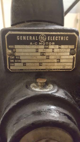
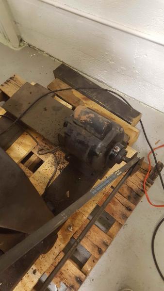
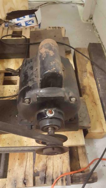
Just about done getting my “new” (1925) C&P up and running. It is currently powered by a electric motor and belt, no treadle. The motor runs fine, but a bit faster than I would like to run at my level of experience (newbie). I have run treadle run presses before and they are a bit more my speed right now. Without having the treadle parts right now though , I am limited to doing runs with the motor. I have seen a few other presses that are motor driven but have a variable speed controller to adjust how fast it runs. I have goggled the topic and of course searched here on how to add one of these controllers in. I have come to the general consensus that being able to add in a controller is dependent on if the motor will work with one. That is where I have come to a dead end. I have not been able to identify if my motor would work with one, and if it will how to wire that in. I have attached a few pictures of the motor, including the make and model. Any input is appreciated!
motor3.jpg
motor2.jpg
motor1.jpg
that “hump” on the motor is a capacitor for start-up. it is going to cause problems in using this motor for any kind of variable speed i think.
1) you could look at a small 3 phase motor using a VFD with single phase input.
2) install a “jack-shaft” to reduce the speed before driving the press. IE the motor drives an “Idler/jack” shaft with a large pulley. on this same shaft is another small pulley. this goes to the press.
You can find websites now that will tell you your present gear reduction simply by measuring the diameters of the drive and driven pulleys. (if you know your math, you can figger it out). the total gear reduction would simply be a 2 step equation.
The drive RPM should be stated on the motor plate, thus giving you the present press RPM, then figuring how much more you want it reduced, would tell you the size of the pulleys needed.
Wow! That’s some great info! I like the idea of swapping the motor out for one that will work with a speed controller. any recommendations on make and model? It will need to power a 10x15 C&P.
Thanks again!
You are better off a little over-powered than under. look for a good used one. do you have Craig’s list?.no more than 2hp would be needed. If going new, “Baldor” here, is a common brand. With the VFD, you can program a “soft start”. this is where the motor starts slowly, then ramps up to set rpm. this is good for older machines.
Presumably the Good Buddy, timed at (03:40) 14th May 2017 must have attended the >Gene Roddenberry< College of Knowledge with regard to Time, Distance, and speed travelled
and the length of the belt.
JUSTY, please elaborate as to just how a “longer belt” or changing the “motor position”, changes final drive rpm.
RPM and pulley diameter are functions of speed. a given belt length, and/or motor position, are not. (at least to my knowledge, but it is 330am here).
Eric M perhaps our Friend meant to say, REPLACE the driving pulley with a SMALLER one (To reduce the overall speed of the machine for the Newbie) which would have/will involve a longer belt.!
But for the learning curve of the original enquirer, the existing pictured system is not exactly High Tech.,! - O. K. the wiring is probably *Jury Rig* pro tem, but will have
H. & S. throwing a >Wobbly<
The existing pulley positioned That Far Out on the output shaft is flying in the face of efficiency, should be as close to the bearing as possible/practical, to avoid undue pressure/resistance on the Shaft & Bearing.
The existing belt appears to be (B) section, usually upwards of 3/4” wide and upwards of 3/4” deep.!
O.K. lays a little more surface area onto the DRIVEN pulley,
BUT also provides massive resistance, wrapping around and inside the smaller (v) of the driving pulley.
With that size motor pictured at 1/2 H.P. (A) section belt(ing) at approx 1/2” - 3/8” wide & 1/2” - 3/8” deep, will, generally, transmit more than enough power.?
you could not go any smaller on the drive pulley and make a difference i think. maybe a pic of the press end, if there is room to go to a larger driven pulley. the motor is placed however, in close proximity to most others using a belt. otherwise, the most effective would be the “jack shaft” suggestion. using that variable width pulleys are available to allow for manual, preset, speed adjustment.
then there is the “whole new motor with vfd”
Fair comment on the possibility of fitting a SMALLER driving pulley, but that tends to be a >double edged sword< in that some traction is lost from the smaller circumference (theoretically) but because positioning the DRIVING pulley farther away from the DRIVEN pulley there is a greater wrap around.! and compensates, up to a point.
IF The V.F.D. system, with relevant motor is plumped for and assuming that it is the Flywheel Proper, that is being driven, the most efficient system for Belting has been found, to drive the flywheel, not the smaller slave pulley{s} because the size, width, and circumference of the flywheel gives almost max. traction and power transmission, coupled with a FLAT BELT Crowned pulley as the Driving pulley.
****Specifically a Crowned Pulley (driving) to keep the belt running ON without any auxiliary guides, GOGGLE Crowned Pulleys,!****
On the Heidelberg Platen because the DRIVING pulley is the >CONED< variable speed type, the Flywheel itself is crowned, the Belt runs true, across the speed range, courtesy of the Crowned Flywheel. - No guides whatsoever, and at over 90” (inches) long has to be proof of the system.!
From the rake and angles of the belt disappearing out of shot, it would seem that the DRIVEN pulley could be the Flywheel,? perhaps J.R. could read and publish the Belt Length, seen in shot 2 (just) Might answer a few more questions for Up-grading, if /when. ? - - Good Luck. Mick.
I can take some measurements of the belt and additional pictures and post here. Any other distances or measurements needed? While I could move the motor a bit in either direction, I still like the idea of being able to adjust the overall speed of the press at any given time. With just moving the motor I might be able to slow the press down a bit, but that does not give me the option to speed it back up a bit on the fly.
That is a fixed speed 1725 rpm single phase motor. It’ll always be that. So far as changing pulleys? Well, you really can’t put a smaller one on the motor, but you would always bulk up (in some way) the driven pulley (ie: main shaft).
For variable speed, you’d be looking at a 3 phase motor VFD combo ($$$) or, have the motor drive a intermediate pulley (that jackshaft thing) with the motor on a sliding mount with a Reeves variable speed pulley on the motor (the kind of pulley on a Windmill motor). Moving the mount creates the variable speed. The jackshaft design conserves your motor torque, whereas trying the start a VFD/motor setup at “slow” is hard on the motor winding (heating).
J.R.D. If circumstances prohibit the expense of V.F.D. etc. as Eric M suggests (above ) *Jack Shaft* assembly, here U.K. we use slightly different terminology but >same animal<
**Jack shaft system as above, but with slight upgrade, can probably be bought Off the Shelf, but NOT rocket science as D.I.Y. with a modicom of expertise**
I.E. Original motor and new *Jack Shaft* mounted as one, on common base plate, 1” thick hardwood if all else is unavailable,! with just the means via slots and Coach Bolts to give fore and aft adjustments, in the order of 1” - 1 1/2”
overall adjustment.?
N.B. with that amount of adjustment available and fitting different length belt(s), the adjustment only has to be +/- (plus or minus) 50% of total required.?
The method basically follows thus:- the motor with original pulley drives a second pulley 20 - 30% bigger, for primary speed reduction, (outer end of Jack Shaft)
Inner end of Jack Shaft carries the eventual DRIVING pulley, (onto the flywheel) calculations via Hand, Brain, &
experiment, BUT coupled with the base plate adjustment (ABOVE) 2-3-4 pulley,s in 1” increments can and will give good initial speed variation(s) with the option of up-rating as the Hand Feed rate, & expertise, increases.
O.K. very crude by comparison to V.F.D. etc., but good for starters, and satisfying,! (if cash flow is limited).!
Good Luck. Mick.
******
The vast majority of all V.M.s, - Vertical Meihle,s employ this very method for speed control,. i. e. The only Motor, single or three phase, drives, in essence, a factored in *Jack Shaft* - counter-shaft in U.K. - The shaft carries the driven pulley from the motor (1) transmits power to the Air Pumps (Vacuum & Blast) (2) and lastly carries a slave Pulley (3) which in turn accomodates 3/4/5 master pulley,s at around 3” - 4” - 5” (sometimes inc. 6”) changed up/down within seconds,! virtually perfect speed control across the required speed range, to suit the stock OR to feed the New Ones in Gently.
One factored in design Plus, when changing up or down, makes no difference,! The starting Handle carries a Jockey Pulley which takes up the slack from the different size pulleys.? Slightly up-market from the suggestion above, apologies. Mick.
this is how mine works
Resized_20170623_122345.jpeg
Resized_20170623_122319.jpeg