Possible restoring of motor/motor questions
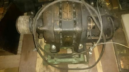
Just some questions about this motor that I got with my press I picked up awhile back. Would like to get it working again as it is a great looking motor. I know I need to either clean the plug-in as it looked like it was corroding or replace it completely. The one thing I wasn’t certain of was this wire looking thing that was broken near the brushes side of the motor that I have no idea what it was for. Any info or tips for this would be great.
client_PART_1484256355102_DSC_0768.JPG
client_PART_1484256363607_DSC_0770.JPG
client_PART_1484319890405_DSC_0774.JPG
client_PART_1484256353562_DSC_0773.JPG
A. T. General ramblings from U.K. perspective (only!) Yes Sir, looks good and probably in keeping with the vintage of the machine.!
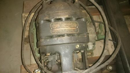
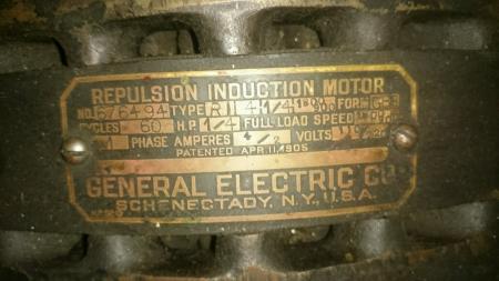
Bumped Up the images posted, there is a wealth of info on the legend/schematic plate, that could be relayed to your (Hopefully Friendly) Electric Motor agents.
I.E. from the plate it appears that it is Dual Voltage and dual speed, 110/240 V. -1800/900 R.P.M.? - Amps., (current drawn) indicated by the 4/2 !
Strong suspicion that the odd wire could be by-passing a broken wire on the mains input, (but in any case NOT entering the commutator housing in that fashion)
Suggest re wiring the entire mains input, with either (U.K. style if available U.S.) Hi-Tuff which is double insulated, with outer insulation in VERY hard plastic, with *Glands* at each end to keep out any thing and every thing liquid based
OR
Double insulated armoured/steel wound cable, also plastic covered and with *glands* and in both cases designed to be flexible, often desire-able if the motor has to swing through an ARC for adjustment(s) !
Apart from the remains of the tag label mounting, appears to be no means for cover protection for the brush gear/commutator, suggest plastic, & shaped cover, stuck on and over but spaced off by 1/4” (ish) to allow ventilation.
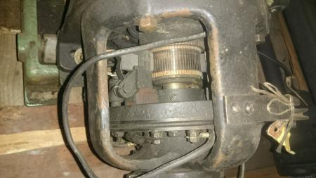
IF You have the above suggested Friendly, electrical motor dealer service agent (short of acquiring a multi purpose Test meter) with just a low voltage supply 12 V. auto battery etc. and just a little instruction it is quite possible to perform *continuity* tests, i.e. across the spade connectors, (pictured) and from the individual spade connectors to Earth and the Frame of the Motor.
Perhaps and before covering the Brush Gear a close inspection of the brushes themselves & the state of the commutator segments, looking for how much or how little carbon still left to play with, usually seen as capacity on the springs to keep the brushes in contact, often verified by the position of the spring within the brush housing.
And a close inspection of the Braided tails that carry the current from the field coils onto the armature/commutator.
The pictured shot of the commutator looks O.K. as far as can be ascertained ? but close inspection may tell how much the the segments have worn down, in relation to the unworn (inner) parts.
Here U.K. it is fairly common practice to (if required) turn the commutator down within certain limits, usually the overall width of new brushes. In new, & replacement form
are completely square faced in approach to the commutator, (soon bed in) but we normally *relieve* the innermost 6 Pt. - 3/16” from the carbon itself to avoid Arcing, whilst bedding in.
Good Luck. Mick
Should have said broken cable near the brushes instead of wire, but the info about the odd cable over there is good to know. Only have the one picture of the broken cable and that’s in the first picture I posted, will have to get a better one of it next time I get the chance to. I have no idea what the cable would have been for, although it looks like it would fit in the pulley channels near the brushes.
Your question suggests a lack of technical knowledge of small electric motors. I suggest that you take the motor to a repair shop to be checked out - trying to fix it yourself could result in a costly mistake - not all small letterpress motors can be replaced at any price.
LD
A.T. (author - Mick) try to make my efforts as comprehensive as possible, in order for You to provide Your Bona Fide dealer/expert with as much info as possible, to talk You through, D.I.Y. as far as possible, pending expensive *Hands On* etc.
I should have perhaps included with the Dual Speed Dual Voltage comments, that as a result of Your >Cable rather than Wire< observation, look closely at the large Collar immediately behind the contact points/input wires pictured 0074 ! the Cable may in fact be the means to advance and retard the entire brush gear (slip ring) for further speed control, possibly corroborated by the 2 part current draw(n), i.e. 4 / 2. But again NOT that point of entry, rather underneath, out of harms way and ending at a small remote lever.
Again and possibly relay this to Your Experts and avoid the need for *in House assessment*
Apologies for the *Bum Steer* info and Good Luck. Mick.
Duplicate. Apologies. STET. !
Thank you for all the information. Even if I can’t get this old motor working again I am still going to keep it as to me it is a work of art.
we have a company here in milwaukee that re builds old motors https://www.dietzelectric.com/.
for a small fee, i would handle your project here locally…
Not sure where your located, but I highly recommend
W. Rosenau rewinding in Sacramento.
Thanks for the recommendations of where to take it. Only problem is I’m in North Dakota so both places won’t work out for me.