Bent Windmill Lay Bar
We have a bent lay bar on our windmill :-(
Apparently the guide slipped to the far end and then when the press closed the lay bar & guide bent around the rail. I did read one thread here about removing the lay bar, and it sounds tricky…with miniscule locking pins on the underside of the screws that hold the lay bar in place. And, it’s not like it’s a super easy place on the press to access. Just wondering if anyone has any experience with this or any words of wisdom before we suck it up and call for a repair. Image attached for reference…
Thanks!
BentLayBar.jpg
Dont touch a thing , this job takes one hour in and out !!!
The block you can see in this image comes out complete with all that you can see attached it is held in place by the block you see here which is part of mor e that is it whole view once removed is shaped like a mallet or hammer the handle of that mallet is the shaft that this is attached by .it is all held in place by two 10mm bolts that are holding it tight in a cut casting that behaves to act like a clamp and two grub screws that hold the part ibn the correct place . to get at the right hand side you need to dismantle the delivery (5 MINs ) pull the delivery back stop as close to the front of the machine as you can you need to reach into the underside of the platen to find the bolt but the grub screw is in the side yuo can never find it in all the muck you must find ths grub screw or you cant pull the lay assembly out you need only the 10mm spanner preferably ring not c type and a metric hex key same on the drive side ,there are no hammers needed at all !! this take less than one hour in and out .
The component you are to remove is part no T0270 and is referred to as a fork bolt
the grub screw on the right going in right to left horizontally and on the one on the left going in left to right horizontally .
The manuals unfortunately do not show the whole assembly its an engineers shortcut as you will never get those taper pins out of the back of the lay adjusters as they are so small you cant id the direction to tap them out which if you hit them you break the whole pin assembly off . the taper pins are not much more than 1/16 of an inch at the fat end !
Thanks, Peter!
I have had one afterthought on the grub screw it may be a screwdriver not a hex key because you would not ordinarily use metric hex keys over there but have a scratch around in there and i am sure you will find out ! As i am not good with the computor you might cosider photographing the process for the others in your predicament as i wwould like to !!
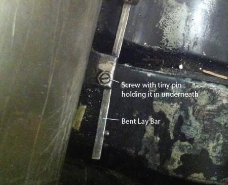
I was recently in the same predicament and thanks to Peter’s help managed to get through it. I thought I’d post a photo to help clarify.
As Peter mentioned, the grub screw is located on the cast metal piece closer to the front of the press. This one is a bit tricky to get to but I managed with a regular size screwdriver (Indeed a flat-head screwdriver not a hex key). Be careful with this because the grub screw is very short, no more than 1/4 inch in length, and can fall out easily into the press. I recommend putting something underneath to catch it in case it falls during removal or replacement.
The other 10mm bolt does not need to be completely removed, just loosened.
Get this done on both sides and your lay bar along with the vertical adjustment brackets should slide out towards the back of the press smoothly.
Hope that helps.
A
laybarremoval2.jpg