The value of broken, fixable things—?
In 2007 I bought a Sigwalt Ideal no. 5 in ready-to-use condition for $800. I think that that was a fair market price at that time. I’m considering purchasing another Sigwalt Ideal no. 5 (for a friend originally, though I’m already in love and don’t want to give it up) which is being offered now, in 2014, for $950. Considering inflation, and the skyrocketing demand for tabletop presses, I think this is a very, very fair price, at least for a ready to use press.
But this one’s going to need a little work. I’m pretty sure nothing is broken, but a bunch of linkages are unpinned, and while I’m mechanically competent, I don’t have extensive metalworking experience, and might need to enlist help to make sure everything’s perfect.
What do you suppose replacing and securing a handful of pins might cost? I intend to buy the press anyway, I’m just wondering if I have any bargaining leverage, and looking for reassurance before I spend a thousand bucks on a pretty, pretty thing that I don’t need (but that I can lend or pass on to a friend who really does need one!)
Thanks!
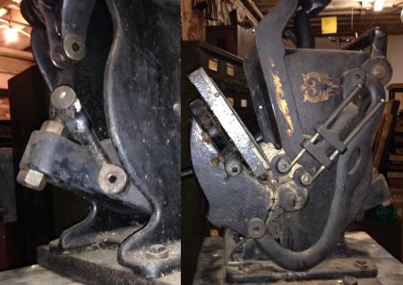
missinglinks.jpg
On my Sigwalt Nonpareil the pin in your left picture must be a friction fit in the outer brackets, as it has no head and no set screw holding it in place. You will need to match the diameter correctly, but you could use a bolt with a sufficient length of straight shank to reach almost through the upper two-holed bracket, installing a thin lock nut on the bolt and cutting off the excess length.
The other pin, for the roller arm linkage, would be a straight steel pin of the correct diameter, and it is held in its hole in the side of the platen by a screw. You could also use a straight-shank bolt for this pin, cutting the threads off short enough so the head is against the linkage when the bolt is fully inserted into the hole in the side of the platen.
Replacing those two pins should be easy given access to a good hardware store, and the ability to measure the hole diameters accurately.
Bob
Pins are basically bits of steel bar but in whatever material required to deal with the stresses of the part they hold , most of your linkages could have brass bar in them as they only drive a pawl for instance but another may require a good hard steel like the link that has your inking roller arms . many will be a common division of 1” so sourcing is not so difficult .
Thanks Bob! At first I thought the repairs looked pretty simple, but I started second guessing myself while trying to rationalize the purchase—I don’t usually spend money on things I don’t need, and I don’t really need this press. But it was love at first sight! And it comes with two complete sets of cores and trucks! One set of rollers has never been used (I’m guessing they won’t be usable now, though, but one never knows). I can’t wait to bring it home!
Peter, both the linkages that are missing appear to have been brass. Perhaps I should use steel instead though, since at least one of the old brass ones looks like it’s broken:
brokenbrass.jpg
Just a few extra hints, (possibly) to save un-needed outlay!!!and more head scratching, it would not be unusual to see, (here in the U.K.) this pictured coupling achieved with, *A* mild steel pin, (catergorically never HARD STEEL, the principle being the pin(s) are sacrificial and not the components???) *B* Silver Steel, (harder but still less than parent material) *C* Brass as pictured!! but in any case 2 dis-similar metals, to aid the sacrificail aspect on the easist/cheapest replacement.
As the Sigwalt is almost certainly, made with Imperial measurements/components, the suggestion would be just with the use of standard twist drills, (normally in sets from 1/16” to 1/2” by using the bottom, (un fluted end) and by hand & finger tip, ascertain the bore/size of the holes in the components, i.e, 1/4” 3/8” 1/2” etc etc.
Once the size is established, simple as obtain, Rod, Brass, Mild Steel, Silver steel, for cents rather than $,s, average hardware/D I Y store etc. (NOT ROCKET SCIENCE) cut with ordinary hacksaw to length plus 1/4”,???, fitted without any other cutting/drilling by utilising non return, retaining washers, at either exposed end, THE TYPE used on Childrens Toys etc etc that are purely a dished washer with 3 or 4 “fingers” that slide onto the shaft and are non return, fool proof, no special tools needed and probably a few cents for pack of 10?? etc.
As there is apparently, no means incorporated for oiling!!! before assembly with new pin(s), on the inner faces of the yoke, with a knife edge file, on either face, file, small grooves less than 1/16” of an inch deep to make oil channels, for the odd squirt??? Not Hi Tech but probably, not included, when the Machines were Made.
Excellent tip regarding sacrificial parts, thank you, Mick! I’m pretty sure I can find brass rods, so I’ll stick with that.
On my other press there is a little bit of wiggle space between the two joined parts along the rod. Perhaps that was thought to be enough space for oiling? Some of the other hinged joints have oil holes.
Gillyfish, thank you, it would have been fairly normal to find, where a common pin shares 3 bearing points 2 + 1 over a component, either permutation of 2 from 3 would involve *A* either a grub screw at the centre yoke to anchor it permanently, to make the arc of the movement, bear the brunt of the wear on the outside 2, or *B* a pin that floated between all 3 and consequently rotated permanently, on every stroke/impression, by implication the means to rotate and move laterally a little, which is where the retaining washers come in.??
If you are able to ascertain, that the bore/diameter of your yoke and its driving arm, are in fact exactly the same that would imply that the original pin was fully floating, and possibly retained by conventional circlips, but from the picture and the broken stub, PERHAPS a previous unsuccessful? repair, i.e. attempting to make a fully floating original pin, fit into an interference fit, in both items, possibly why it gave up originally?? . . Possibly a target for re-assembly, fully floating to distribute the wear around 360 degrees.
Little wiggle, not surprising, when the age and usage is taken into account, generally not too critical as wear is normally only on the pressure stroke, wears the bores egg shaped/elongated!! lost motion not so important and expected, BUT if , (for example) the travel of the rollers is compromised up or down, (more so down, to clear the chase and inking) consideration given, to precision drilling and/or reaming the wear, out, to the next size up, (possibly as little as 1/16” of an inch) and bigger pins, to suit!! .
Apologies if this be considered rubbish, but may help a little. Good Luck Mick
If the original pin was brass then refit brass ,i havent read the later added post but i think mick has made a good point using the word sacrificial ,the reason that pin is brass is for it to save other more serious parts from breaking ,they are what in short are called “shear pins ” Designed solely to burst under overload ,these must break and having looked at the pic of your press again i would think they should be able to shear if overloaded ,better that and its quick fix than having to try repairs to castings …
I seriously doubt that the brass pin was original. I just took a file to the end of the pin in my Sigwalt’s impression link, and it appears to be steel. That pin takes the full brunt of the pressure of printing, and I suspect brass there will severely limit the amount of pressure you can apply in printing, because it will shear more easily than steel. If you plan to try to do deep impression printing with that press I would even go so far as to use high-strength steel, like drill rod. The other pin for the roller arm link, doesn’t have near the stress on it and could be brass, but I don’t see any reason for it there as there is not likely to be any more resistance to that part than the friction of the rollers riding up on the ink disc.
Bob