Is C&P Secondary Flywheel Necessary?
Hello,
I’m looking to pick up a C&P old style in the seattle area and notice that it doesn’t have the smaller flywheel on the right side (smaller than the large main on the left and usually set down and back from the gear on the right side of the machine).
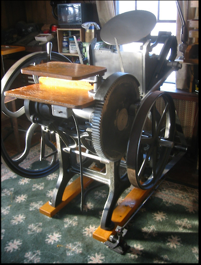
When it does appear in photos, it looks like it is belt driven by the motor, but I’ve seen many without the smaller flywheel. What do you think, is this important? Is it missing? Or did it never come on this model?
I’m including reference photos: the first is without the flywheel, the second has it included.
Thanks,
Corbinw
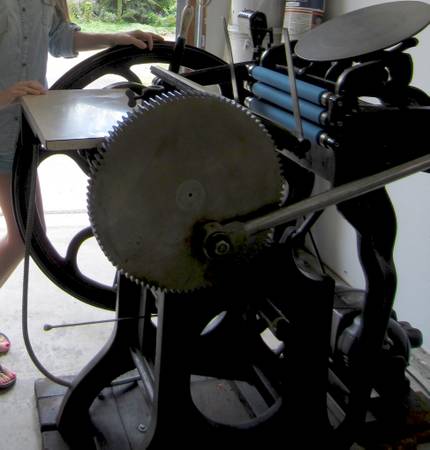
Kent_Press.jpg
Screen Shot 2013-07-12 at 11.35.43 AM.png
You can run the press without the smaller wheel, only problem is you can’t hook up a brake, I’ve had some with and some without the smaller flywheel and never had a problem.
All the C&P brakes I’ve seen worked on the main flywheel, so it you drive the press with a belt on the main flywheel you couldn’t use that sort of brake. Sometimes the smaller wheel (which really isn’t a flywheel but a pulley) is mounted on the left side next to the flywheel also.
Bob
Thanks, guys! That helps a lot.
Corbin
The big flat surface pulley, usually with flat leather belt, found on old presses was referred to as the steam pulley. Reportedly (that means I have not actually seen it) several presses may have been run from one power shaft. That shaft may have been behind a wall and was powered by a steam engine. A horizontal rod below the throw off lever was used to engage and disengage the belt and power shaft.
Might have been fun to run such a press and hear the steam engine.
I’m sorry but you can run a brake on the main flywheel AND a drive belt as well. I have that set up on two presses, one with a two inch fiber belt and the other with a V-belt. If anyone has steam fixtures for an 8 x 12 C&P and would like to sell them, I could really use them when we run a press with a “hit & miss” engine.
I have a press with a smaller pulley/flywheel on the right side of the press but it has no function other than making it easy to wash the press from the right side and being able to rotate the press.
C & P Flywheel, generalisations, NOT FACTS! in the heyday and of the time period of these type of machines, motive power would have been more limited than now, consequently the first option would have been, flywheel standing alone as the only flywheel to maintain momentum, on one side of the machine with foot operated brake with leather brake pad operating on the underside of the flywheel, consequently on the other side of the machine would have been, one fixed and one free pulley operating from overhead line shafting, powered by remote gas engine, steam engine, or similar. This would have been considered desireable because the thrust on the PLAIN bearings would have been shared equally from side to side, but of course that necessitated extended shaft on both sides, which would still be desireable today, for motorising purposes! For the same reasons and to accomodate flywheel brake? Next in the line of progression would have been individual base mounted motors per machine, D.C. with speed control and then A. C. but still using 2 pulleys fixed/free controlled on the machine. And then on up to date a whole host of ingenious adaptions, force of circumstances or availability? One common adaption which does not look right or perform too well is where the flywheel is driven with a “V” belt from a very small pulley on the motor which gives very little wrap around on the driving pulley and is prone to slip under load/impression, and generally the main/only flywheel proper is NOT slightly “convex” to keep the belt “V” or flat running on. One recent adaption appears to be bolting an aftermarket driven pulley to the flwheel, which would still seem to be transmitting a lot of thrust on to one probably well used bearing on one side. The foregoing implying several ways to achieve power transmission, circumstances/prowess and money dictating which route! tried to provide a few possibilities. good luck.
I have eight presses that I run with a V-belt on the main or left flywheel and have never had a problem with slippage nor with the belt staying in place if the motor is properly aligned. Yes, it may not look right, but it works just fine.
Like you John. I too have run C&P’s for years with a V-belt and brake on the same flywheel. As long as it is in alignement
no problem No problem with slippage or anything else.
Winfred Reed
Black Diamond Press (KY)
Some info from the C&P booklet published by the agent Samuel Stephens of Boston - extra attachments not included as standard - side power attachments. If the press was to be operated as treadle only, the drive pulleys mounted on the right hand side were not required. The specs also list two different pulleys, a loose & tight pulley (regular power fixtures) for a line shaft system and a larger single pulley for an electric motor.
Another option available was the friction drive using an electric motor but this required the special milled flywheel.
It appears that a brake was not available from C&P, however other manufacturers were providing them. An advert for an American Job Press Brake is on page 1071 of the American Line Type Book 1906 by ATF. It states that belts may be run on the flywheel if desired.
Malcolm
The largest Thompsons had a flywheel on each side of the press for the sake of maintaining inertia on forms requiring more physical force.
I’d imagine that the additional mass of an off-side pulley, if large enough in mass and diameter, could also have a useful effect in reducing motor strain at the moment of impression in the cycle. I wonder if it might even make treadling more pleasant once the press was up to speed!
Does anyone have one of these presses with the double flywheels?
Dan
J.H. & W.R. with respect, anybody who is anybody, with some knowledge and/or longevity knows or understands that you CAN turn input pulleys/flywheels/shafts via a myriad of different methods (being a loose description for adaptions, bodge ups of necessity, or circumstances etc) but as “V” belts were not invented when most of these machines were in their prime, my humble efforts are trying to give the new ones a picture of the original design and construction. So that there is some basic original concept as a starting point. The learning curve is surely easier with this in mind! It is noted that a couple of little discreet disclaimers have been included, one each? Instead of belittling my efforts why not get in first with the real deal, to help the one(s) that want to know and “pull the tooth, the whole tooth, and nothing but the tooth” With the genuine basic original picture in mind, modern adaptions can be treated and appreciated as such???
The comments were made that, “you can’t run a brake and v-belt on the same flywheel together”. Although, I know what these posters meant, that you can’t run them together using the manufacture design. But you can with a little ingenuity.
I wasn’t trying to belittle anyone. Now that is the real-deal.
And apparently not ” anybody who is anybody, with some knowledge and/or longevity knows or understands that you CAN turn input pulleys/flywheels/shafts via a myriad of different methods (being a loose description for adaptions, bodge ups of necessity, ” knows that or the question would not have come up!
Ha! Mick are you sure you haven’t eaten some bad gator lately.
Winfred Reed
Black Diamond Press (KY)
I’ve run c&ps for over 50 years and never saw one with a belt on the flywheel with a brake also, but after checking out mine I can see with a little tweeking it can be done. Never to old to learn something new. Winfred, I called you a while ago, got no one, i’m glad to see you posting. Dick G.
The simplest method to have brake action on a flywheel belt set-up is to adapt the caliper brake mechanism commonly found on bicycles. I had such ‘Rube Goldberg’ device on a new style C&P, and it performed flawlessly. (But ensure it is anchored firmly to the floor!) There’s always more than one way to skin a cat. :o)
Hey Dick. I’m in & out all the time. Sorry. I’ll try to call you this week. I tied up the next two days with funerals.
Winfred
2 flywheels does make treadling easier. Of course there isn’t room for a drive wheel…
CandP.png
Bill nice press! How many kicks per impression does it take?
Girl, it depends on where you kick it.
Girl - I treadled up to speed, then stepped off the treadle; counting how many non-impression rotations until it stopped. The second flywheel added about 1-1/4 rotations over just one flywheel, which by itself was good for about 2-3/4. Your mileage may vary - depending on lubrication, etc.
I think Girl was talking about how many times you must depress the treadle to achieve one impression. On an 8x12 C&P it will be 4 times, and I believe on a 10x15 it is 6 times. I don’t know if the 12x18 or 14x22 are different than the 10x15.
Thanks again for all your help. I’m picking up the press tomorrow and moving it into my shop.
The plan is to use a floor crane (engine lift) to set it into the back of a pickup truck. Anyone have experience using a floor crane to lift an 8x12 to bed height?
You’ll want to hook it onto the crane with the boom as low as you can get it. It also depends on the height of the truck — they differ. If you can work off a sidewalk with a curb and have the truck sitting on the street level you’ll gain several inches. It’ll probably be close.
Bob
One possible tip and I have done several times, with an engine crane/hoist it is desireable to strop it or shackle it, as close up as possible, taking care to protect small outcrops from crushing, when lifting. As engine hoists traditionally have to lift clear of car/auto bodywork, the gib invariably ends up high and above the horizontal, making the weight of the machine act like a pendulum, when attempting to track onto your flatbed. I learnt the hard way ONCE! where practical and/or possible drive the flatbed/truck, under the machine, rather than vice versa. If you have to track the machine and gantry, to the truck lower the machine via the hydraulics to within 4-6 inches ground clearance, and perhaps, remember, that the longer the gib is extended the more unstable it (the crane) becomes. Canvas, Nylon, or similar straps/strops and “D” shackles. !! NOT chains or ropes, 4 point lift and if necessary, baulks of timber as spacers to stop crushing. on lift. Some machines Thompson, Heidleberg for example have a removable plug high up near the ink cylinder for introducing a substantial eye bolt/ring bolt etc for single point lift! Might it be worth a quick investigation on your machine, as way back there was incorporated in the main frame castings, both sides! 2 aligning holes for a substantial rod/tube ABOVE point of balance to accomodate lifting facilities.
Thanks again for all the input! The move was a success without incident. We lifted the press with the floor crane and backed the 5x9 U-Haul trailer right under it. We just reversed the process when unloading. The press is in great condition, I just had to tap the flywheel back into position and grind a new key to keep it in place. Couldn’t be happier with this old beauty.
Photo-Jul-22,-7-30-46-AM.jpg
Way to go! Good move and a good looking press safely in its new home. Congratulations!
Bob
The machines come in many various configurations, some with a streight axle, some with a throw for a treadle, some with no stub axle out the right side, some with a short stub some with a long stub. If there is no stub the only way to drive the unit is off the main flywheel. With the stub varying speeds can be attained with different diameter pulleys, also there was available, had one on my press a clutch ie variable speed friction drive with wooden friction drive shoes and a brake assembly. The drive would engage by lifting the lever to the desired speed (sometimes required some tweeking) and pressing the lever all the way down to apply the brake. There was a brake surface and clutch surface in the same hub assembly. I have seen presses run in either direction does it matter? Dave
Has anyone ever used a motor with a rubber hub/wheel driving the main flywheel with out a belt.
I was wondering if I could construct a device that held a motor and by stepping on a pedal/lever I could have the drive spindle with a rubber wheel turn the flywheel. Releasing the pedal would drop the motor so it is no longer contacting the fly wheel. I’m thinking it would only be in contact when your foot was ” on the gas” so to speak.
Any thoughts????
Q, As above.
A, Yes makes for a very efficient marriage.
With a little technical proviso, = as (generally) smaller capacity motors single phase OR three phase come in 2 distinct variations, Frame Size and number of *poles* usually governing the relevant output speeds, as in 1,420 or thereabouts (R.P.M.) and 2.800 (R.P.M.) or thereabouts, both Pro Rata produce the same output, but for the proposed use above, fitting the faster (2,800 R.P.M.) machine gives a distinct advantage in that there is a lot of Torque to spare, and is gentle on power consumption.
+ with the added advantage of output speed, and the *Driver* to *Driven* ratio, makes the initial flywheel rotation, a doddle.
Our method for the friction drive is as simple as, once the size of the *driving* pulley is determined approx, whether it be Cast iron, Steel, Alloy, Nylon, or whatever! we just >Bond< superglue etc, a TYRE, to the pulley made from a strip of redundant Litho blanket. canvas back rubber faced, works perfectly.!!!! … Mick. Dec. 2016.