Golding Official No 12
Hi all,
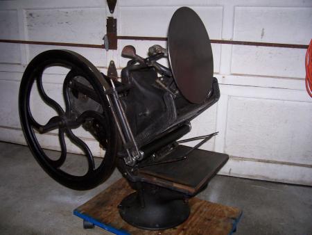
I picked up this press (Golding Official) along with a Pearl and some spare parts and wanted to get to the vast network of experts. It appears to be complete. I have a gear guard, springs, and some bolts that are not reinstalled on this picture. Seems to have some extra parts not normally on the No. 12 Does anyone have any experience with one like this? Any help like pictures, diagrams is appreciated.
Thanks
John
Perennial Designs
Copy of Official no12.JPG
Can you post more photos? The press seems to missing its base which looks like a old-time cast iron stove along with foot treadle and connecting links. If you want to contact me off list:
platenpress at sbcglobal.net.
Paul
Paul,
Is this a Golding map press with a flywheel??
Hi Paul and John,
Just checked in to see any responses. It has a stationary platen, so I believe it has to be the larger map press. It’s chase matches the No 12 at 8.25x12.5. I don’t think it is missing a base Paul. I think it has extra iron that allows for the addition of the flywheel instead of a stirrup handle. That part I’m talking about is just bolted into the frame and actually was broken on this press. I was given a second one for parts and have replaced the broken part already on the better press. This one was being driven by a motor which I have also. I need to build a sturdy table to get it all back together and working. I can post more pictures later. Need to run a errand. I sent pic to Stephen O Saxe and he had not seen one like it. Oh, I almost forgot, It does say Official and Golding on a casting! It is one heavy tabletop!
John
John,
Take a look at page 143 of Hal Sterne’s second edition of the Catalogue of Nineteenth Century Printing Presses, or the Golding Official Rotary in the Briar Press Museum, to see what Paul meant by the base — I’m sure your press originally had a similar base, though Golding evidently sold the Pearl Old Style with the shipping crate designed to be used as a base. If you plan to run the press motorized a base probably isn’t necessary, but for treadle operation it would be.
Bob
I am sure it is a Golding Official Map Press. I don’t know if the flywheel attachment is part of the original equipment, even if the owner has another press like it. I await more photos especially to see where the flywheel attaches to the press and how it turns the press over. How many revolutions of the flywheel for one revolution of the press?
Hi Bob,
I have looked at the Official Rotary in the museum several times thanks. (don’t have the book) This press certainly could have had a similiar base but I just found this picture and caption on the APA site. Caption: The Official Imprinter (Mapping press) was made in Treadle and lever models. The press pictured looks like mine with the flywheel, not a lever yet it is mounted on a board which begs the question where a treadle was mounted and connected.
John
25mapping_press.gif
Here are some requested pictures. The flywheel cycle is about 3 1/2
John
golding3.JPG
golding2.JPG
golding1.JPG
John,
You have an Golding Official Imprinter. This one and the one you have for parts are the only two that I know of in existence. I have both a #12 Official Map Press and an Official Rotary. Neither is quite like yours. Since you seem to have it together, unless there is a specific problem I don’t know how anyone can help you.
If you ever want to sell the parts press or this one I would be interested. Where are you located?
Regards,
Paul
Hi Paul,
I am located in Lyme, CT. and I hadn’t thought about selling, but, I may consider it. Do I understand you correctly that the model is an Official Imprinter which is something different than a No 12 map press? The only problem I have is minor and probably I can figure it out. I am not sure what spring controls the gripper bar and where it connects. Also that component is different on the two presses. One press is obviously older than the other and has a couple of minor differences. thanks very much for your very helpful information.
John
Old Lyme, wow, Did you find the press in state?
John,
In the third photo there appears to be a screw hole on the side of the press visible between the lower right spokes of the flywheel. If that is a screw hole not presently in use it is probably where the gripper spring was attached. I assume the gripper bar has a rod on the other side that rides on a stub on the side of the press to operate the grippers. I also see something that looks like it’s attached on the other end of the gripper shaft and hanging down — on the regular Official the gripper spring is attached to a cotter pin in a hole in the base below the arm, so perhaps that’s the case here as well.
Bob
I just got my network back up after having to replace my dsl modem.
Lammy, Yes, right here in CT. I purchased a Ludlow, a Pearl No 11, the Official Imprinter and spare parts press, a foot operated perforator, and a lot of Pearls parts, Ludlow parts, and some other items. I am attaching a couple of pictures of the haul.
Bob,
You’re very observant! Those holes are for two large springs that mount on each side and help counter balance the weight of the bed as it comes down on the platen. It makes a print cycle much smoother. I hadn’t reinstalled them in this picture. There is a hook that protrudes on each side of the base that is where the other end of the heavy springs attach. There is a gripper rod, and on each end is a straight lever as seen in the third picture(golding1.jpg) and the two new shots. The other side has the same straight lever with a spring attached only on the lever. They both have set screws to adjust the position on the gripper rod. There is nothing on either side of the press that turns or positions the gripper rod/grippers as the press cycles as on my Official no 2, Pearl no 11, or my CMC Jobber. I am attaching two more closeups of what I am trying to describe.
100_2865.jpg
100_2864.jpg
100_2863.jpg
100_2862.jpg
100_2861.jpg
John,
If you ever need a hand with anything let me know. I’m not to far away, though nothing in this state is LOL. Now I also know where to go to trade my old casting metal for new slugs ;)
John,
It would be helpful to be able to examine the press in person. As the bed comes down something has to pull up/back on those two levers (I suspect they are not positioned correctly) to close the grippers. I’m guessing that the gripper spring was attached somewhere near the boss where the large springs are — if it were there, as the press closes that point goes up and would pull the gripper lever with it, closing the grippers. Could there have been another piece in that mount that had an eye for the smaller spring?
Bob