Identity of half tone cut?
Hello all,
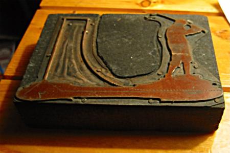
I have a series of very old half-tone photoengraved wood-block mounted cuts. I know they’re old because I remember seeing them in my dad’s workshop as a kid. They are unusual (to me) because they are a rosin color and not a metallic silver or grey color. Can anyone offer any information to me as to exactly what KIND of half tone cut this is? Are they valuable or just “old cuts”? As always, thanks to this esteemed group!
halftone.jpg
The plate you have attached is a copper halftone plate. The silver-colored materials you may have seen are zinc or magnesium. Copper was the standard material used for better quality halftone images.
There was also a method by which duplicate plates could be produced by the electrotype process, but plates produced by that method would have a copper surface with a lead or typemetal background. If you were to scratch the area that is routed out on the plate you have, if copper, it should gleam with a reddish, copper color, if lead, would be a bright silver color.
As explained by j H they are electros , lead base and eloctroplated in copper to harden the wear face . Many companys produced them even sold by adana and others from pattern books , i believe foundries may have produced them but i have little knowledge of them other than printing off them , i make paper dirty ,the origin of the stuff to do that was another part of the trade . I know bits about the comps department as it was in the same hall but as for the finer details it was not my field, Type comes in three distinct styles ,fat ,thin and leaning over and i can recognise about a dozen fonts !
One other possibility is that the brown is a light sensitive acid resist coating which is still on the image areas. Sometimes it takes a while for this coating to wear off during the printing process. If that is the case, this is probably a zinc engraving.
For a newby novice, please explain what is a half-tone plate?
thanks
to print a picture you had to shoot the picture thru a screen to break it into fine dots, this is called a halftone.
To elaborate on what dickg said….
A black and white photograph actually has shades of gray in it, as well as, usually, dark areas and white areas. We call this type of reproduction “continuous tone”.
Reproducing a photograph presents a problem for us as printers, because we only have two options when putting ink on a sheet: if we put ink on the sheet, it comes out black. If we don’t put ink on, the sheet is white. We can’t put on small amounts of ink on at the same time, and get various shades of gray.
So, we have come up with a way of fooling the viewer’s eye into thinking that we are printing shades of gray, even though we actually aren’t. What we do is break up the picture into tiny, evenly spaced dots which most people don’t notice. Where we want to create the illusion of light gray, we print very small black dots. Where we want to create darker grays, we print larger black dots. Where we want to print an area which trends evenly from light to dark, we slowly increase the sizes of the dots from one area of the paper to another. This type of reproduction is called a “halftone.”
If you look at a printed black and white picture with a magnifying glass, you should be able to see the dots.
Since all the dots are solid black, we are able to print a picture this way because it only requires us as printers, to print solid black or nothing, which is what we can do with our presses.
In summary, where a photograph has actual shades of gray, a printed picture has different sizes of dots.
to LetterpressDad and others
Some decades past, we often had guided tours of the newspaper plant where I worked. Usually a compositor was given the task. After some difficulty in explaining some processes, I photocopied a black-and-white pic of a person’s face, but greatly enlarged; we had a good photocopier which gave a clear image; then I stuck it to the wall at the end of a 30ft long room, and asked visitors to look at the pic from that distance, then close-up. Now, I wonder if I could do the same with a full-colour pic, although that gets somewhat more expensive; we have a good colour copier at a stationery shop here, and I have got some good results, but balancing the colour at $2 a time does make one very selective; wish I had photoshop available, one comp took the mole off a person’s face once, and the person then had cosmetic medical attention to remove the mole after seeing the effect; or did someone remark on the mole?
Also, after we moved to cold type, our second variety of photosetters used a b&w cathode ray tube; I found in the book a description of the way the machine made type, using vertical stripes, and enlarged the explanatory image. One group was deaf children, the “minder” communicated by sign language, and had a problem translating my comment that the cathode ray tube cost $17,000.
When we had Linotype, we used to set up a long line of matrices in a certain order, then get the visitor to stand up on the step at the back of the machine, to be startled when ALL of the matrices left the distributor bar simultaneously; doesn’t work with Intertype.
Alan.
Tangential to the thread, but if the Intertype has the same keyboard layout as Linotype, the same keyboard combination should yield the same result. The only way that Intertype could achieve market acceptance was to follow the lead set by Linotype, otherwise it would have been a real oddball.
Doesn’t help that either machine had six or seven major keyboard arrangements, and customers could specify their own as well.
to mikemontana and others
OK, I was writing about matrices dropping off the disser bar of a Linotype; most models of the Linotype had a disser bar with equal spacing between the drop-off points; the channels in the magazine were of even separation and width. The Intertype machines which we (later) used had a disser bar with unequal spacing between drop-off points, and varying separation of the channels in the magazine (and varying-width spacing of the channel entrances); thus we could use a main magazine (on one machine) with 24-point duplex-display matrices on the machine along with ordinary text 7-point, the equivalent of Linotype Ionic No 5 (or Ionic No 7 — my memory is not good), in another (main) magazine, without any changes to the Intertype except mag and mould and knife etc. [No auxiliary magazine/s.]
Later we got a display Linotype (heading machine) which used matrices (the larger sizes) with the lugs of some of the matrices NOT in alignment with one side of the matrix, thus offsetting the matrix in SOME of the channels in order to fit the wide matrices into an ordinary width (90-channel) main magazine.
Earlier on this saga, we had a heading machine [with normal-style main magazine and tapered side magazine/s (34 channel?)] which had seen a lot of use. The bottom rail of the distributor bar fell off along part of its length; the auxiliary combination was still in good condition. The agents found a bar in West Australia, only some (5000 k) 3000 miles (my guess) away. When it arrived, it was for a machine with normal main mag (OK) but also for a narrow mag with parallel sides (no taper, 28 channel). The operators were able to use the machine with this, but had to remove any auxiliary magazine matrices before they reached the distributor box. Then one operator thought about this, laid a length of [elrod or monotype?] strip on top of the channel entrances to the auxiliary magazine/s so the matrices did not drop; I do not remember if these auxiliary-magazine-matrices still ran on the disser bar, or if the disser screws were the only contact with the matrices; this worked very well, the matrices for the auxiliary magazine/s were carried across to the pi tube, and put back in the auxiliary mag later.
Next, the good but incorrect disser bar and the failed disser bar (which still had a good auxiliary combination) were sent to the agents in Brisbane (only 500 miles direct flight), so that the two bars could be cut and put end-to-end to make the combination so essential. When this two-piece disser bar came back, it had been cut wrongly (and badly) so it was then taken to a local (country town) metal-working shop, with an explanation of what was needed (and probably our engineer on hand to watch); when installed this time, it worked very well.
Has anyone seen a machine lose a combination rail of the disser bar in this fashion?
Alan.
P.S.: I could have added a couple more stories to this, but refrained. — A.
Love your stories, it jogs my memory, i remember sending a line that all the mats would run across the distributor then drop all at once, then there was a line we would set where the mats would drop one at a time, can’t remember how they were set but its been 30 years since i ran a linotype.