C&P Pilot Roller Issues
Hello, so I can’t say I have inking issues. It seems as though my press mostly inks plates up just fine. I’m currently using a Boxcar deep relief with K152 plates and now that I’ve got my rails taped, most of my work seems to print fine.
I do feel like I’m having some issues with my rollers, though, which can sometimes cause an uneven inking. The rollers appear to be crooked (see photos below), and then they slide from left to right in the saddles as they move downward over the ink plate to rest below the chase when I’m making a print. Even if I put the rollers in so that the ends of the metal rods are flush with both saddles, they end up sliding left over time so that more of the rods stick out from the left saddle than the right. This tends to pull the whole roller over so that my metal trucks on the right side drag across the ink plate.
What is causing this? Do I need new springs to make my saddles tighter? Is one roller arm loose? Do I need new rollers and trucks?
Like I said, I’ve been able to print 1250 2-sided, 2-color business cards just fine so far, with the exception of some lighter inking on the left side (where the rollers slide more).
I can also make a video and upload it to Flickr if anyone would find that helpful for troubleshooting. Thanks.
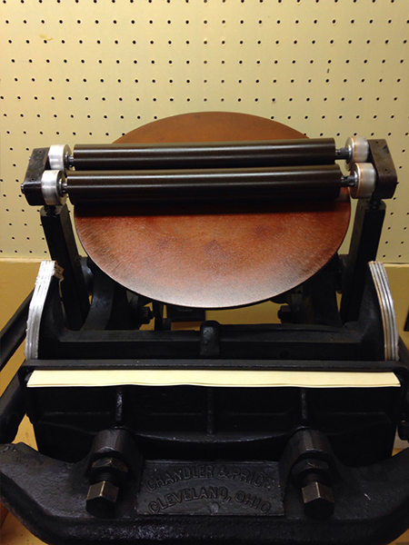
cppilot-roller-issues-001.jpg
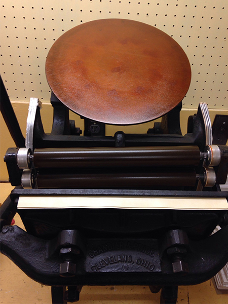
cppilot-roller-issues-002.jpg
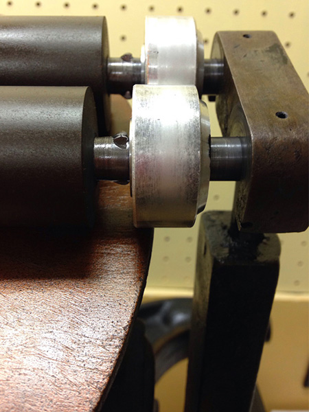
cppilot-roller-issues-003.jpg
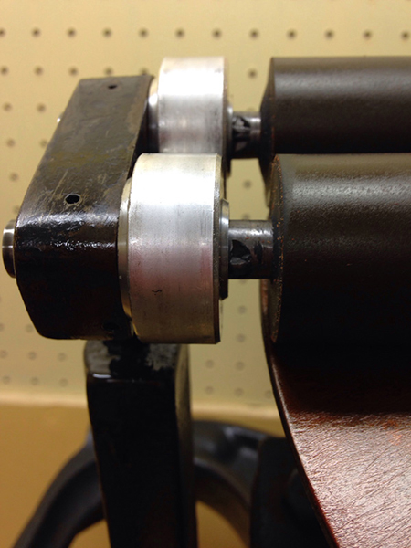
cppilot-roller-issues-004.jpg
You might want to order a set of new roller trucks from NA Graphics. The correct ones will fit over the nubs on the roller cores and also be wider to keep the rollers balanced between the two saddles.
http://order.nagraph.com/roller-trucks.html
DGM
Oooh … those trucks from NA Graphics look completely different from the trucks I have now! What what? I may have to just place an order right now.
Since your trucks aren’t fitting properly on the roller cores you’re probably seeing some torquing in your roller arms. Hence one side being higher than the other. New trucks from NA Graphics should solve the problem.
Brad.
H N Sir, it appears that the right hand side roller carriage arm may be out of sync with the left hand side equivelant???
Just a test, possibly, if you bring the rollers of the disc and just before they pass over the top bar of the chase is the gap equal over all, (flashlight and a white paper behind to observe, 3pt. 6pt.12pt leads or reglet as feeler guages) should that verify out of truth, have the arms, side to side lost their register, Loose Bolt, Worn Taper pin etc.
If this should be an issue?? it would have the effect of dragging the roller(s) to one side, (in essence acting as a one way reciprocator by default)??
As their have been many posts, regarding taping the rollers/trucks many many times, and as new and REMANUFACTURED are turned to other than normal standard size, to elleviate the taping problem, why not bite the Bullitt and have new ones turned oversize by .002 - .005 for example, NEVER TAPE again!! and it is not Rocket Science to figure out with .005 tolerance in hand packing the form to meet the compound of the rollers must be far more Hi-Tech than taping with the plethora of materials as posted here-in, to quote, *Plastic insulation tape, Masking tape, Litho plate strips, Bean can strips, Leather,* etc etc etc Apologies for possible Red Herrings.
Verify truck diameter—when we inherited the business, there was more than one diameter of truck being used on Pilots and it was very confusing. People came up with their own standards.
This press appears to have roller arm problems that causes the skew effect. The arms are held on with one taper pin each and as these presses age, the holes the taper pins go through will wear and that allows the arms to move. It is not a really good set up to begin with. I looked at the Pilot press we have here and the rollers are no longer firmly attached to the rod or shaft that takes the taper pin. I would think that the holes would have to be redrilled and re-reamed for new taper pins for a tighter fit, but that is a machine shop operation.
Fritz
Don’t expect the roller trucks you order from NA Graphics to look like the photo on that link. Those are Morgan Expansion Rollers. What they supply for the C&P Pilot are delrin plastic. I don’t have a set of them here to photograph, but they are dimensionally identical to these original metal ones and work just as well.
DGM
I would also suspect the problem delineated by Fritz. Check to be sure the taper pins are fully seated, and then check for movement of either roller arm. It’s possible that A) someone substituted a different pin for the standard ones, or B) as Fritz says the holes are worn.
You can also help prevent the roller migration (after you fix the roller arms) by putting washers on the cores between the trucks and the hooks, which will prevent the rollers from migrating. Just be sure there is a little play to prevent binding.
Bob
Thanks so much for the suggestions, everyone.
I will investigate the taper pins first tonight. I don’t know of a machine shop here in town that will work on letterpress machines, but the Book Arts Center here should be a good resource for contact info should there be someone to lend a hand.
Since this is an Old Style C&P, I can only imagine what parts are more worn than others. It spent an uncalculated number of years on someone’s front porch as well. While a good cleaning and lots of oil has definitely brought back its happy luster and performance, I did have to replace the yoke pin and spring because they had rusted to pieces. I would not be surprised if something else, like the taper pins and/or their holes, also needed some loving care.
I noticed some side to side roller migration on my Pilot as well after a restoration and solved it by shimming with some nylon washers (Home Depot) as suggested above. I’m also running a deep relief base and K152 plates. My trucks are the delrin ones from NA Graphics.
Any machine shop should have a tapered reamer for the taper (there are different tapers so if you can remove one or both pins for samples you’ll be better off). If the holes are slightly worn reaming out a little and using the next size larger pin should get you home. You might also consider getting a little bottle or tube of Loctite and reinstalling the pins with that to keep it all together.
Bob
Nifty,
I am not sure that your problem starts with the rollers. The first picture shows the right side roller is further up the press than the left. It indictates to me something is out of sync. One way to isolate the issue and confirm if it is about truck size would be to rotate the roller and trucks, left to right. If the roller size is your problem the shifting should move to the opposite side.
My guess is this has more to do with the movement of the arms.
Steve V
Are the springs gummed up? Take the rollers out and pull the saddles up. Do they move freely?
Girl with a Klulge - the saddles move freely! Thank you. They seem well oiled and not gummed up at all.
Everyone else, thanks again! New trucks are in the mail, so that will be one experiment. I’ll pick up some washers next time we got to Home Depot as well.
Can anyone post a photo of where to look for the taper pin? I tried to look at the C&P Manual online, but I couldn’t find reference to that pin (saddle pin?) and it wasn’t clearly marked anyway. I’d appreciate it!
H. N. Sir, If you are convinced that, *A* you have loose/worn taper pin(s) but their is no evidence *B* of at least one end of one pin showing wear or minute gap, Before disturbing that which may NOT Be the problem, standing behind the machine and with both hands on each arm, try for any evidence of play in the pins, which you state that you cannot see as yet!!!
If you feel play with just gentle pressure, then as the pins may well be obscured with years of ink and wash up, and with the use of either a hand held wire brush, or a rotary based wire brush, in your electric drill, hopefully expose the taper pin(s)
Unfortunately they are, usually, ex factory and D.I.Y. aftermarket, inserted (tapped in after reaming to fit) the easiest way in (down hand!!) by implication the hardest way out?? . . The principle seems to be B****R the next owner, lets get rolling, most of us are /have been, guilty.!!
If it should prove to be taper pin(s) or the shaft worn out of sight internally, and you have exposed the location of the pin(s) you should be able to determine which way out to remove, even with judicious use of dentists style mirror or examine with arms at fullest travel!! in both directions? WITH CARE and assistance.
If you have to call in Engineer experts!! with all the will in the world make sure that, not only do you get and need a good, reamed taper pin repair, but register/synchronisation is important!!!
Usually your general Engineers although they do a brilliant job fitting Taper Pins, Roll Pins etc,(i.e.) to gear shifts and similar, have the benefit of of auxiliary adjuster(s) for syncro, which you probably/generally dont have on Small Presses from a long time ago!!!…
If you have to go to the extent of washers as well, perhaps, with enough gap to spare or take up, alternate washers with stainless steel with nylon?? good friction free arrangement to help your rollers!! Good Luck.
I would expect the pins holding the arms to the cross shaft to be perpendicular to the length of the arms and in the center (left to right) of the arms, centered on the cross shaft. Since they are (theoretically) tapered pins, one end will be larger than the other. You want to tap on the small end to drive the pins out, after, of course, you have determined that one or both are loose. You could also try tapping the large end in to seat the pins if they have worked loose — if that fixes the problem I would suggest removing the pins and reinstalling them with Loctite.
Bob
On the O.S. Pilot there are also Dutch pins found driven into the roller frame shaft from the ends. To find these one must remove the roller saddle shafts after pulling the pins from the shafts compressing the roller saddle springs. These Dutch pins are also tapered. During some O.S. Pilot restorations we find these pins missing. Though I could argue that they aren’t necessary for proper operation of the press, I do believe they had a purpose during assembly of the press. I believe the purpose was to ensure the two roller frames were in alignment before the cross tapered holes were drilled.
Their presence or absence may be moot in this case.
I want readers to know of their existence should you need to remove the frame from the shaft. Since the roller frames on this press are clearly not aligned there could be several causes. The point I want to make is… before reaming a hole be certain the frames are aligned.
I have found a roll pin inserted into the correct sized hole to be an adequate replacement for the tapered pin.
If any reader ever needs help with the Pilot press, please don’t hesitate to contact us.
Tom & Terri
www.tandtpressrestoration.com
Hi,
I’ve been in the engraving field for over 30 years and I’m interested in building my own scale model of the C&P Pilot Letterpress. I’ve searched the internet for specs on part measurements and have not been able to locate them anywhere. Would anyone have this information and be willing to share it?
Thanks,
Ron